RS-1_instruction manual.pdf - 第476页
Part 1 B asic O peration Chapter 4 Cr eating a Produc tion Progra m 4- 141 4.4.2 .1 Checking the divided component placement d at a This section de scribes how to dis play the plac emen t data divided with the Opt imizat…
Part 1 Basic Operation Chapter 4 Creating a Production Program
4-140
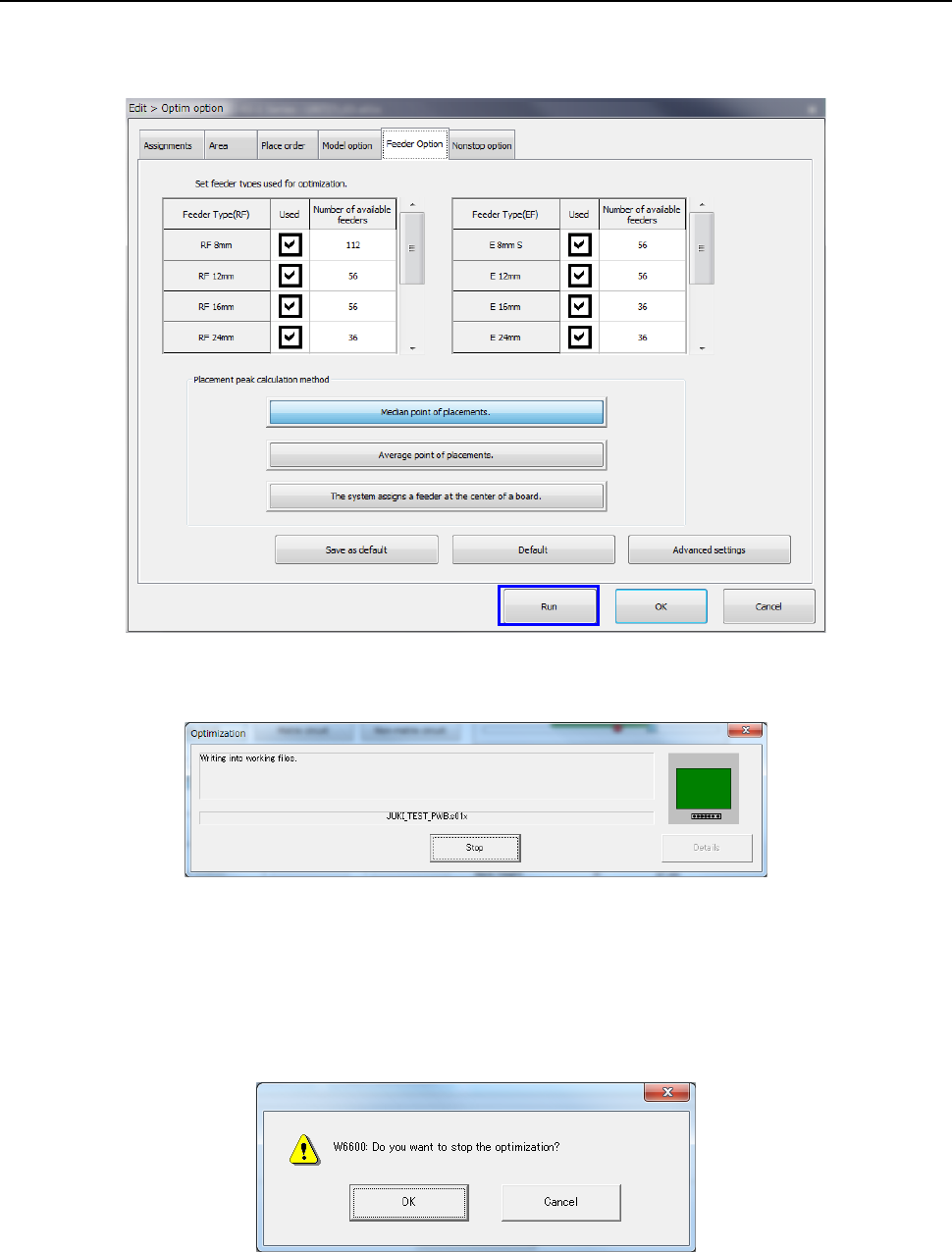
4.4.2 Executing the Optimization function
When you select the <Run> button on the “Optim option” (Optimization option) dialog box, the
optimization processing starts.
The following screen is displayed while optimization is executed.
When the system finishes the Optimization function normally, the “Optimization” screen
disappears.
If an error occurs during optimization, the corresponding error message appears on the screen.
When you select the <Stop> button during optimization, you can stop the optimization.
When you select the <Stop> button, the following confirmation message appears on the screen.
Part 1 Basic Operation Chapter 4 Creating a Production Program
4-141
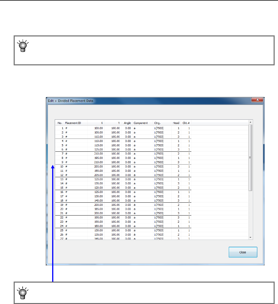
4.4.2.1 Checking the divided component placement data
This section describes how to display the placement data divided with the Optimization function.
Select the [Optimization] command from the menu, and then the [Divided placement data]
command from the “Optimization” menu.
• You cannot select this command if you have not performed the Optimization function
(that is, there is no divided placement data file), or if you edit a production program after
executing the Optimization function.
The “Divided Placement Data” dialog box appears on the screen.
• A bold line on the “Divided Placement Data” screen in the optimized order indicates a
delimiter of data paired during one component pick-up and placement cycle.
Part 1 Basic Operation Chapter 4 Creating a Production Program
4-142
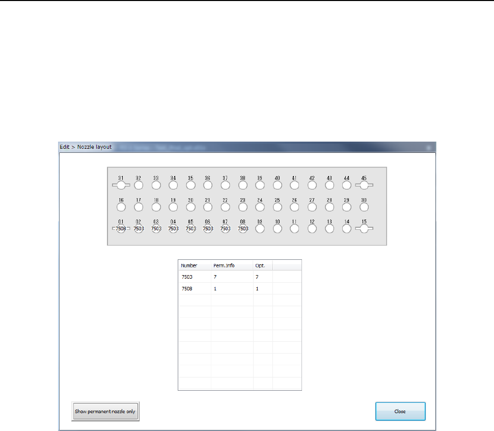
4.4.2.2 Nozzle layout
The [Nozzle layout] command displays the nozzles assigned to each station with the Optimization
function.
When you specify “Auto arrange nozzles” in the “Nozzles” field of the “Assignments” option screen,
check the result on the following screen, and set nozzles so that the nozzles can be assigned in
the same way specified on the “Machine setup” menu.
When you select the [Optimization] – [Nozzle layout] commands, the “Nozzle layout” screen
appears.
The following “Nozzle layout” screen appears.
a) Nozzle layout diagram
The nozzle layout output with the Optimization function is displayed here.
If any nozzle not shown on this nozzle layout is set on the “Machine Setup” screen, it is
indicated in red on the screen.
b) ATC Device
Select the position of the ATC to be displayed, the front or the rear.
c) Nozzle information
Number: Nozzle numbers are displayed here.
Perm. Info: The number of nozzles set on the “Machine Setup” screen is displayed here.
Opt.: The number of nozzles output with the Optimization function is displayed here.
d) Show permanent nozzle only
This button switches the “Nozzle layout” screen to the screen indicating the nozzle layout
set on the “Machine Setup” screen.