RS-1_instruction manual.pdf - 第1044页
Pa r t 2 D et ail ed Des c r i p ti on of Each Function C hapter 1 3 Supp l em en t ar y I nf o rm ati on f or C r eating a Production P rogra m 13 - 21 Log to ol 13. 7 For mak ing a f ailur e analysi s, thi s f unc tion…

Part 2 Detailed Description of Each Function Chapter 13 Supplementary Information for
Creating a Production Program
13-20
Laser status list 13.6
- Shown below is the list of status that is returned from laser when it obtains the result of your
clicking of the <Meas. (ONCE)> or <Meas. (SWEEP)> push button as the “Control item” on
the “Laser control” dialog box.
Status
Description
0 Indicates that the command was finished.
1 Indicates that the command was normally executed.
11 Indicates that the left-end window is covered. Check he component position.
12 Indicates that the right-end window is covered. Check he component position.
13 Indicates that both-end windows are covered. Check the component position.
20 An error occurred in communication with LNC120.
21 The communication with LNC120 could not be established successfully. Check whether LNC120 is correctly
connected. (The IP address may not set correctly.)
22 A component can always be detected on the laser. The nozzle may be too long or the laser surface may be
damaged.
23 No component can be detected by lowering the Z-axis.
25 An error occurred in axis movement during laser measurement.
26 An error occurred in communication with the laser sensor but the communication was restored.
27 An error occurred in communication with the laser sensor. The communication could not be restored.
Restart the machine.
28 No shadow could be detected during measurement.
30 An illegal parameter was detected in the command.
31 Illegal data was detected.
32 Laser recognition could not be completed.
33 Measurement resulted in an error for other reason.
34 The encoder input error. Check the encoder cable and connector for contact.
40 In the data received from the laser, a packet number error was detected.
41 In the data received from the laser, a command error was detected.
42 In the data received from the laser, an address error was detected.
43 In the data received from the laser, a data number error was detected.
44 In establishing communication with the laser, a timeout error occurred.
45 In receiving data from the laser, a timeout error occurred.
46 In sending data to the laser, a timeout error occurred.
47 In sending data to the laser, a retry-over occurred.
50 In ONCE recognition processing, a recognition error occurred.
51 A sensor error was detected during ONCE recognition processing.
60 Though measurement was not executed, a request to obtain a measurement result was executed.
61 No measurement data could be obtained.
62 A request to obtain a measurement result was executed during measurement rotation.
63 A request to obtain a measurement result was executed during measurement rotation.
64 Correct data for measurement could not be obtained.
65 Measurement cannot be performed because the center of rotation of the object to be measured is out of the
center of measurement.
66 Now, measurement is interrupted.
67 Enough data for measurement could not be obtained.
68 A request to obtain a measurement result was executed during measurement rotation. (During door angle)
70 The sensor was executed unless the laser was initialized.
71 An unexpected error occurred in the laser.
72 Measuring processing cannot be executed because the set window size is small.
Part 2 Detailed Description of Each Function Chapter 13 Supplementary Information for
Creating a Production Program
13-21
Log tool 13.7
For making a failure analysis, this function records the operation status of the equipment and
stores its result as a file.
If any trouble occurs, get its log (error occurrence history) by the following operations.
Please get the log at once upon occurrence of trouble because the log may not be overwritten if
another operation is continuously performed.
Getting a run time log 13.7.1
A log of the running program is got.
Get log:
Saves a run time log. This log is saved under ¥LOG¥Save according to the following naming
rule.
YYMMDDHHMMSS.log
YY: Year (2 lower digits) MM: Month DD: Day HH: Hour MM: Minute SS: Second
Part 2 Detailed Description of Each Function Chapter 13 Supplementary Information for
Creating a Production Program
13-22
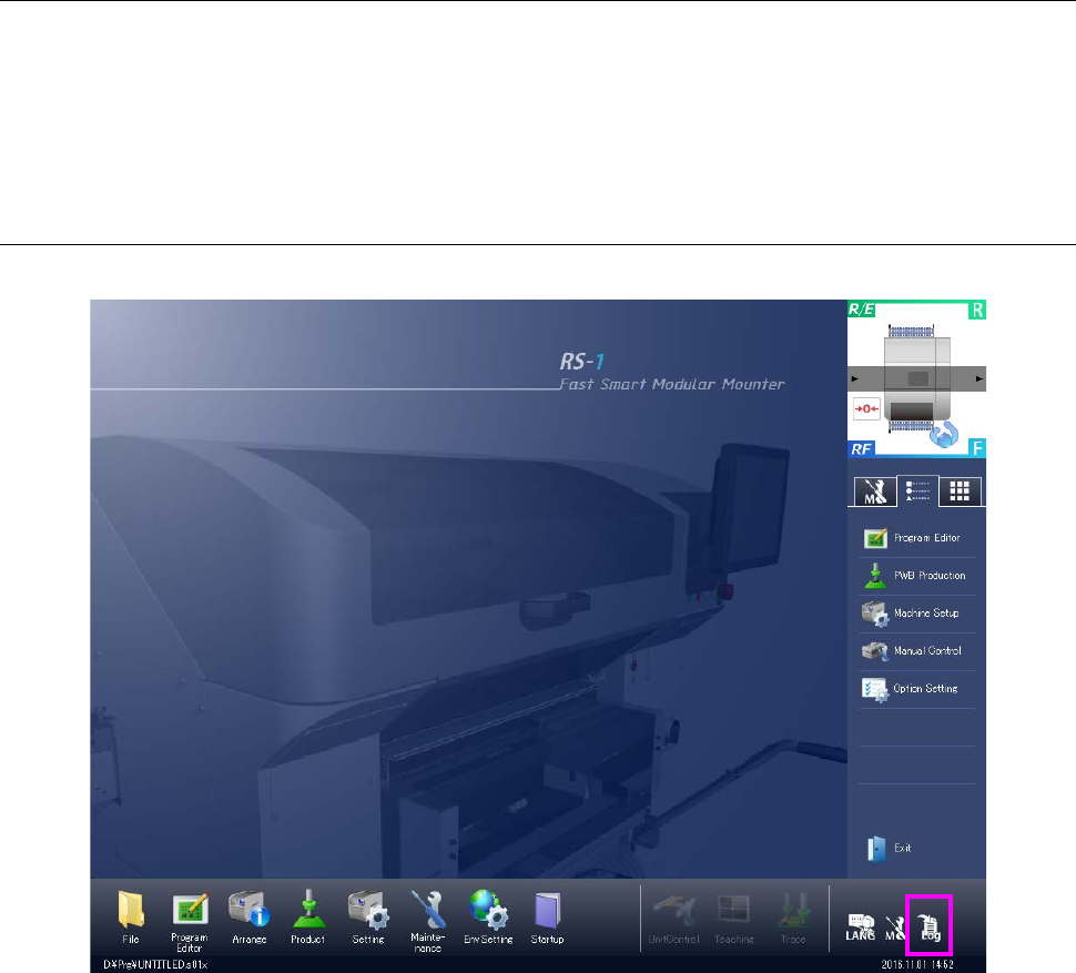
Getting a maintenance log 13.7.2
Get a maintenance log (operation log/event log).
Select [Maintenance log] in the “Maintenance” menu.
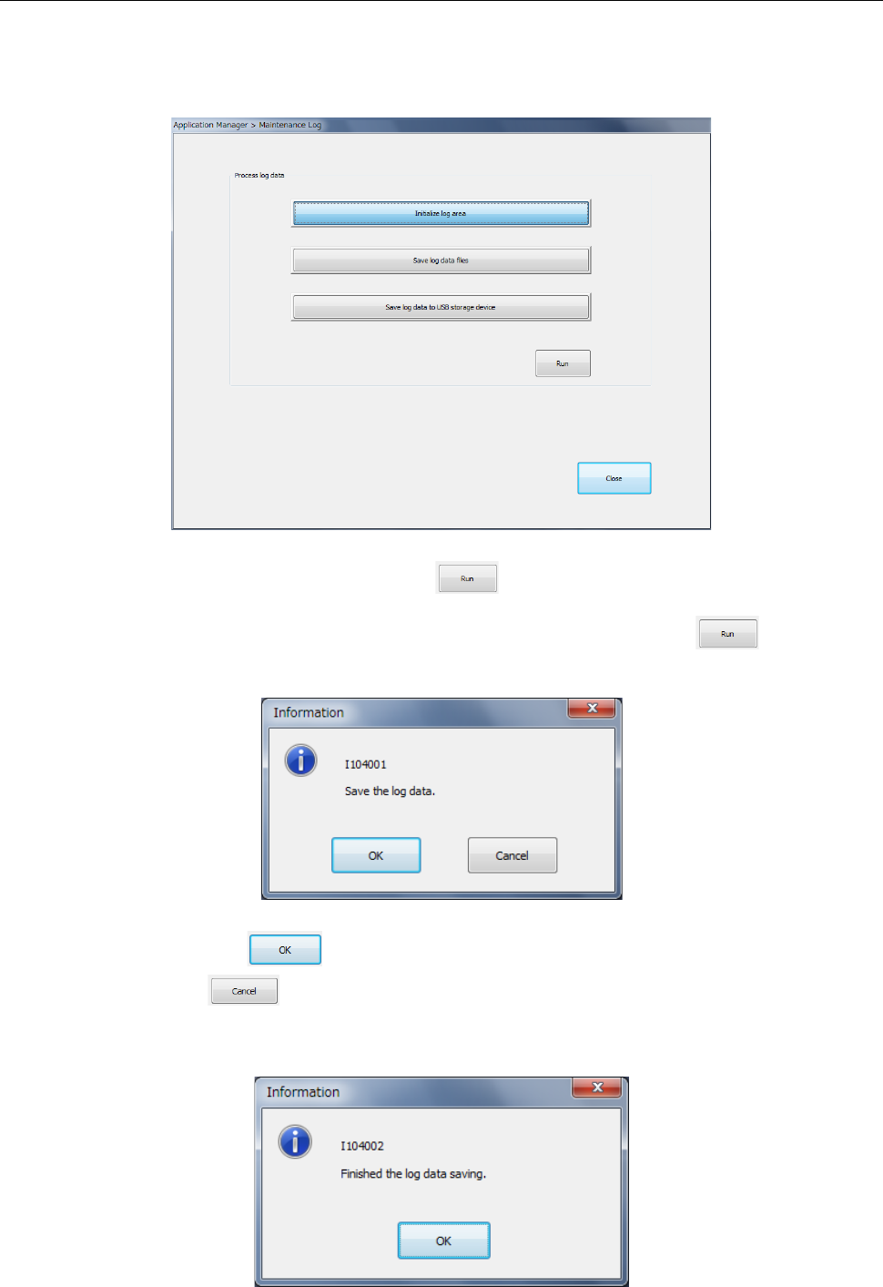
The log is initialized or saved into a file.
Select <Initialize log area> and press the button. Then, the contents of the existing
log are cleared.
Select <Save log data files> or <Save log data into USB> and press the button.
Then, the verification message is displayed.
When you press the button, saving is executed.
If you press the button, the data is not saved and the system is returned to the
previous status. After saving is completed, a message is displayed
(Folder for saving a log: D:¥JUKI¥LOG¥MaintLog)