RS-1_instruction manual.pdf - 第637页
Pa r t 2 D et ai l ed Des c r i pt i o n of Ea c h F unc t i o n Chapte r 6 G e neral - Purpose Vision Co mpone nt 6-6 Examp le 1 : Multi - le ad c omponent Examp le 2: Co mp lex - arr ay comp on ent 3) Layout i nspe cti…
Part 2 Detailed Description of Each Function Chapter 6 General-Purpose Vision Component
6-5
Creating an Element group/Element format 6.2.1
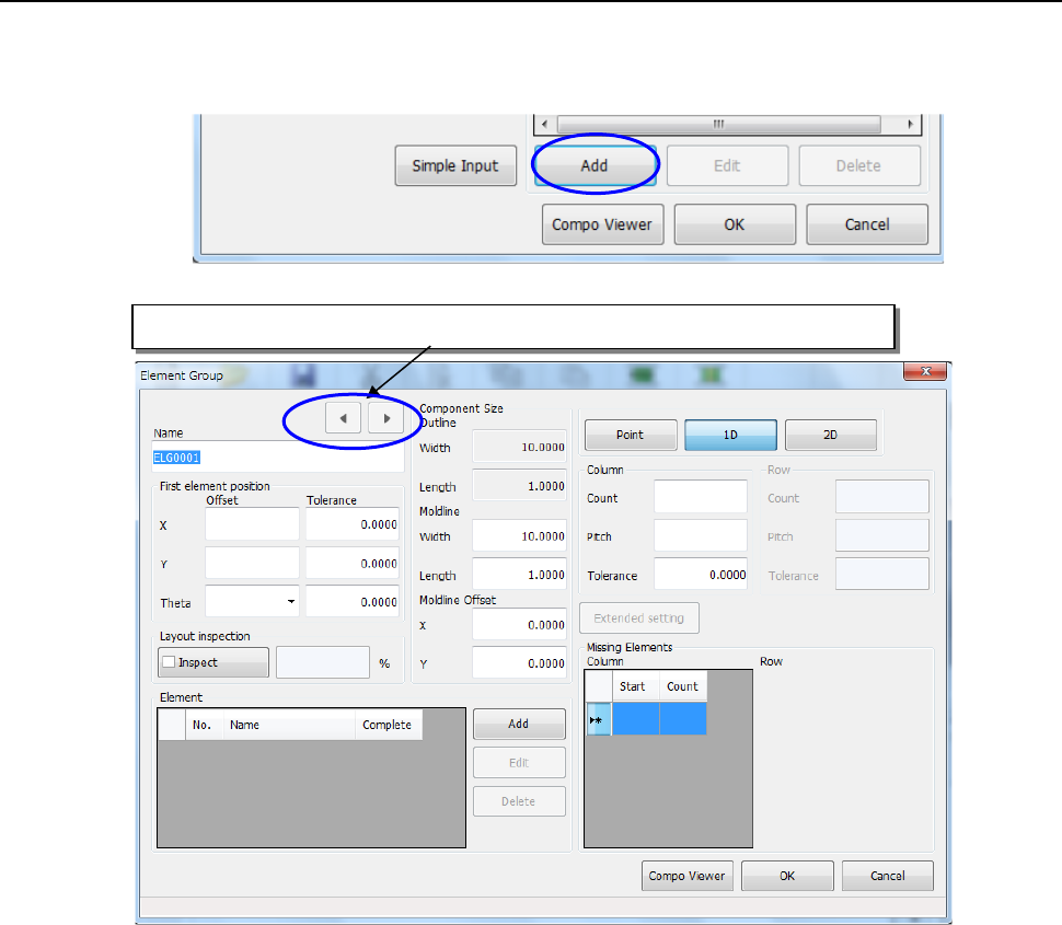
When you touch the <Add> button on the “Element Data” setting screen, the “Element Group”
creation screen appears.
(1) Name:
Enter up to 32 alphanumeric characters to specify the name of an element group.
(2) First element position:
Enter the distance between the center of a component to be recognized and the first
element.
• Offset
− X, Y: For a multi-lead component, enter the distance between the component center
position and the center of the tip of the first element. For a complex-array
component, enter the distance from the component center position to the center
of the first element.
* Be sure to enter the dimensions correctly. If an error of the distance
between element groups exceeds ± 0.05 mm, the system may not recognize
the element groups.
− Theta: Enter this field for a multi-lead component only. When a lead is located on the
bottom side, enter “0°.” For the right side, enter “90°,” for the top side, enter
“180°” and for the left side, enter “270°.”
• Tolerance:
Although you can specify the tolerable range of value to be set, do not change the
initial value “0.” Be sure to use “0” for all “Tolerance” fields of the element group.
Clicking either of these buttons displays the previous or next element group data.
Part 2 Detailed Description of Each Function Chapter 6 General-Purpose Vision Component
6-6
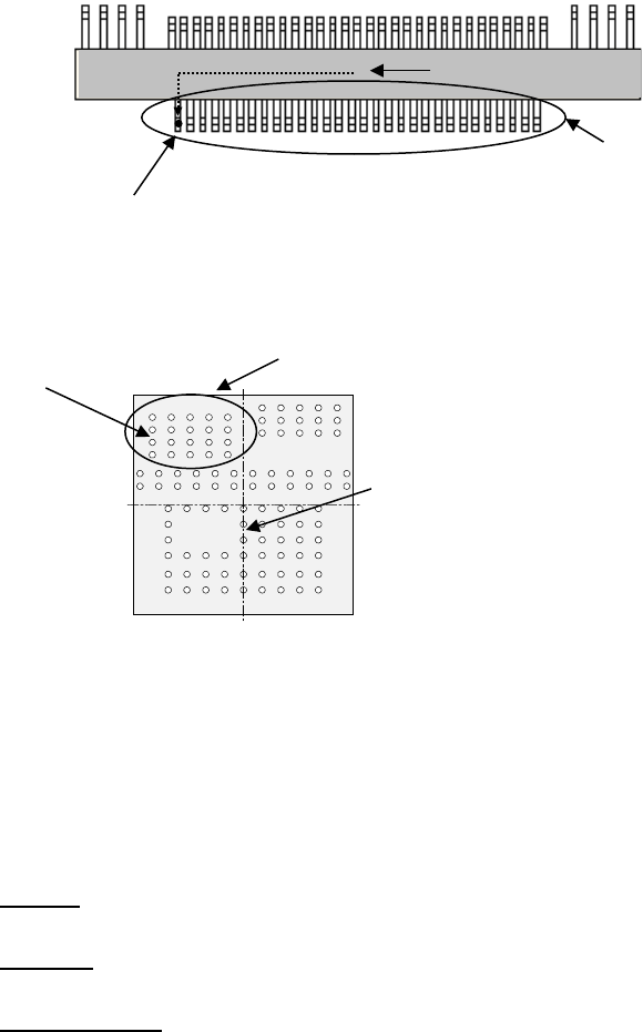
Example 1: Multi-lead component
Example 2: Complex-array component
3) Layout inspection
Set the tolerant range in which the center can be shifted with considering a lead pitch or ball
pitch.
4) Component Size
When you enter data to these fields for a lead component, the system can open the
Component Viewer (see Section 6.3) correctly.
• Outline:
Values entered on the “Component” data screen appears here.
• Moldline:
Enter the dimensions of the molded section of a component.
• Moldline Offset:
When you enter data to the “Moldline” and “Moldline Offset” fields, the system can display
a lead component more correctly. This function is provided for the Component Viewer
only. If you do not enter any value to these fields, the dimensions of a component
appear on the Component Viewer screen.
5) Point, 1D, 2D
• Point : Select this radio button if there is only one element in the element group.
• 1D : Select this radio button for a component such as a lead component whose
elements are placed in a line.
• 2D : Select this radio button for a component such as a BGA whose elements are
placed horizontally and vertically.
6) Column, Row
When you select the radio button “1D” or “2D,” enter the number of leads or balls, and the
pitch.
Bottom View
部品中心位置
(
外形中心位置)
First element position (Θ = 0º)
Element group
Center of a component
to be recognized
First element position
Element group
Center of a component to
be recognized
Part 2 Detailed Description of Each Function Chapter 6 General-Purpose Vision Component
6-7
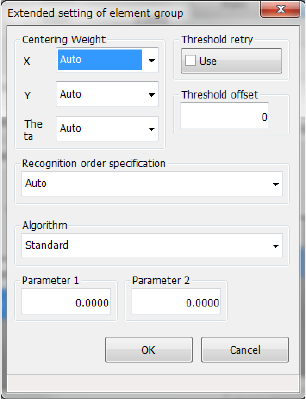
7) Settings on the “Extended setting of element group” screen
Make extended data settings of each element.
Centering Weight
Set weighting of each direction: X, Y and theta.
“Weight” means weighting of an element group for positioning a component. If you set a
smaller value in this field for an element group of a component whose accuracy is low, the
component can be positioned stably.
Set a value from 1 to 100.
Threshold retry
Turn on/off the retry operation activated with a threshold value. For example, if you turn it
on when the contrast is unsatisfactory, a recognition error may be fixed.
Threshold offset
In the same manner as contrast correction for recognizing the outline of a component, you
can set a threshold offset. If a component cannot be recognized stably with a threshold
value automatically calculated, set a threshold offset here.
Recognition order specification
If a component is recognized stably when you specify recognition order, set the recognition
order here. Normally, do not change the setting “Auto.”
Auto: does not specify the recognition order.
Definition order: recognizes components in the defined order.
Algorithm
Set the algorithm for a side, a corner and a lead. For a component whose outline is to be
recognized, coarse positioning of a component is added to the standard algorithm to
improve the response capability for a positioning error and an irregularly-shaped component.
You can select the conventional algorithm also.
Other elements are parameters for expansion in the future.
◇ Standard: uses the standard algorithm.
◇ Conventional algorithm: uses the conventional algorithm.
For other elements, you can select an algorithm to perform the recognition when a part of
the lead component is hidden by sheet metal or the shape base matching (3rd) is used in
addition to the standard algorithm.
◇ Standard: uses the standard algorithm.
◇ Algorithm 1: Performs the recognition with the DOG filter in addition to the coarse
positioning with other elements.
◇ Algorithm 2: Performs the positioning recognition with the DOG filter in addition to the
coarse positioning with the shape base matching (3rd).