RS-1_instruction manual.pdf - 第959页
Part 2 D etaile d Descript ion of E ach Functi on Chapter 12 Handling th e Optional Device s 12 - 75 (4) E xecut e verify inspection af ter splicing. Check to see if the “Exec ute verif y inspect ion after spli cing.” ch…
Part 2 Detailed Description of Each Function Chapter 12 Handling the Optional Devices
12-74
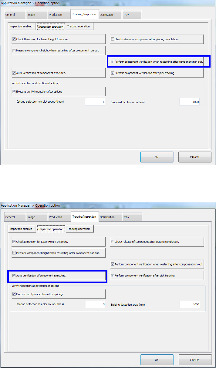
(2) Performing component verification when the system restarts after components run out
Make sure that [Perform component verification when restarting after component run out] is
checked off in the same way as (1).
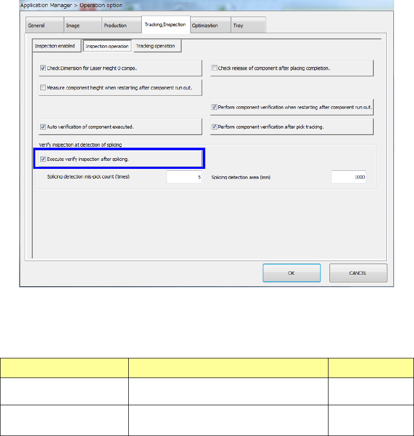
(3) Auto verification of component executed
Make sure that [Auto verification of component executed] is checked off in the same away as
(1) and (2).
Part 2 Detailed Description of Each Function Chapter 12 Handling the Optional Devices
12-75
(4) Execute verify inspection after splicing.
Check to see if the “Execute verify inspection after splicing.” check box is checked off in the
same manner as (1), (2) and (3).
When you select the “Execute verify inspection after splicing.” check box, you can make
settings of the “Splicing detection mis-pick count (times)” field and the “Splicing detection area
(mm)” field.
Setting item Description Input range
Splicing detection mis-pick
count
Specify the number of mis-picks for
detecting a spliced positon.
1 – 100
Splicing detection area
Specify the detection area for detecting a
spliced position.
500 – 10000
Part 2 Detailed Description of Each Function Chapter 12 Handling the Optional Devices
12-76
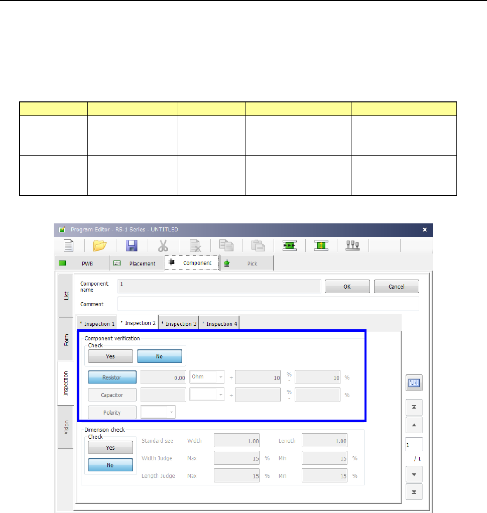
12.12.2.3 Editing Component Data
Specify whether to verify a component and set the value to be used for judging the inspection
result on the “Inspection” tab of the “Component” data screen.
To set the supplying direction of a component that has a polarity such as a diode, regard the right
side viewed from the front of the machine as “+,” and the left side as “-” when the component
supply angle is 0º.
For details, refer to “4.3.5.2.(7) Inspection 2.”
Input range
Unit
Upper limit
Lower limit
Resistor 0.00 to 999.99
Default: 0.00
Ω (default)
KΩ
MΩ
0 to 100 %
in increments of 1 %
Default: 10 %
- 100 to 0
in increments of 1 %
Default: - 10 %
Capacitor 0.0 to 999999.99
Default: 0.00
pF (default)
μF
0 to 100 %
in increments of 1 %
Default: 80 %
- 100 to 0
in increments of 1 %
Default: - 20 %