RS-1_instruction manual.pdf - 第38页
Part 1 B asic O peration Chapter 1 Overv iew of the Machine 1- 20 (3) M inim um comp onen t width (D) of e ach compo nent ⑥ SOJ ① Square chip ② MEL F ③ Al uminu m electr olytic cap acitor D = A + 0.5mm ④ SOT ⑤ SOP ⑦ QFP …
Part 1 Basic Operation Chapter 1 Overview of the Machine
1-19
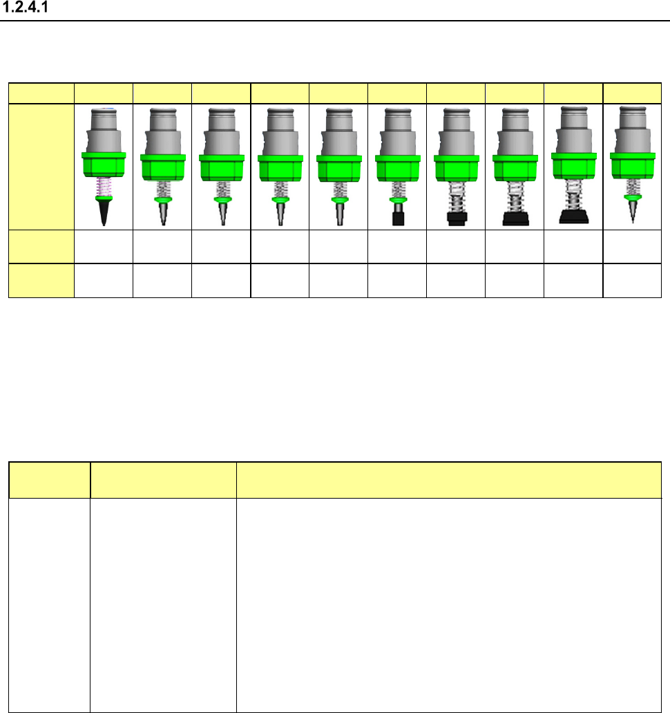
Nozzle
(1) Shape of nozzle
Select the nozzle from No.7500 through No.7509, according to the shape and size of the
components to be mounted.
NO.
7500
7501
7502
7503
7504
7505
7506
7507
7508
7509
Appearance
Outer
Diameter
1.0x
0.5mm
0.7x
0.4mm
φ0.7mm φ1.0mm φ1.5mm φ3.5mm φ5.0mm φ8.5mm
10.0x8.0
mm
0.2x
0.4mm
Inner
Diameter
2x
φ0.4mm
φ0.25
mm
φ0.4mm φ0.6mm φ1.0mm φ1.7mm φ3.2mm φ5.0mm
8.5x6.5
mm
φ0.1 mm
(2) Nozzle selection
The nozzle can be automatically recognized if you follow the explanation of "ATC Nozzle
Selection." If you manually select the nozzle, select the nozzle with extreme care to prevent
poor pickup and placement of a component.
The nozzle numbers for major types of components to placed be are shown in the following
table. However, to keep accuracy of pickup and placement, select the appropriate nozzle No.
by referring to the minimum size of the suction area of each component.
See the item (3) for the minimum width (D) of the sucked area of each component.
Nozzle No.
Minimum component
width (D)
Major types of components
7500
0.45 to 1.45
1005, 1608, SOT (Molded part: 1.6 x 0.8), 2012<Note>
7501
0.45 or less
0603
7502
0.45 to 0.75
1005
7503
0.75 to 1.45
1608, SOT (Molded part: 1.6 x 0.8), 2012, SOT (Molded part: 2.0 x 1.25)
7504
1.1 to 2.5
2012, 3216, SOT (Molded part: 2.0 x 1.25), SOT23, Melf,
7505
2.5 to 4
Aluminum electrolytic capacitor (small)
tantalum capacitor, trimmer
7506 4 to 7 Aluminum electrolytic capacitor (medium)
SOP (narrow type), SOJ,
connector
7507 7 to 10 Aluminum electrolytic capacitor (large)
SOP (wide type), TSOP, QFP,
PLCC, SOJ, connector
7508
10 or more
Q F P, P L C C
7509
0.2
0402
Note: Theta offset may be caused by pick surface shape of 2012R (depending on
manufacturer, resistance value, etc.) For high-density mounting (adjacent
clearance of 0.3 mm or less of components 2012, use nozzle 7504.
Note:
When recognizing the square chip image, Be sure to use a CVS nozzle to prevent a
component from being recognized by mistake.
Part 1 Basic Operation Chapter 1 Overview of the Machine
1-20
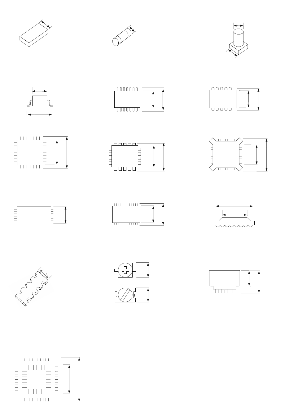
(3) Minimum component width (D) of each component
⑥ SOJ
① Square chip ② MELF
③ Aluminum
electrolytic capacitor
D = A + 0.5mm
④ SOT ⑤ SOP
⑦ QFP
⑫ BGA
⑧ PLCC ⑨ BQFP
⑩ TSOP
⑪ TSOP2
⑬ Network resistor ⑭ Trimmer
⑮ One-way lead connector
⑯ Gull wing socket
J lead socket
Socket with bumper
A
D
A
D
W
D
A
D = A
A
D
A
D
A
D
A
D
A
A
D = A
A
D
A
D
A
D
A
D = A
D
A
A
A
D = A
Part 1 Basic Operation Chapter 1 Overview of the Machine
1-21
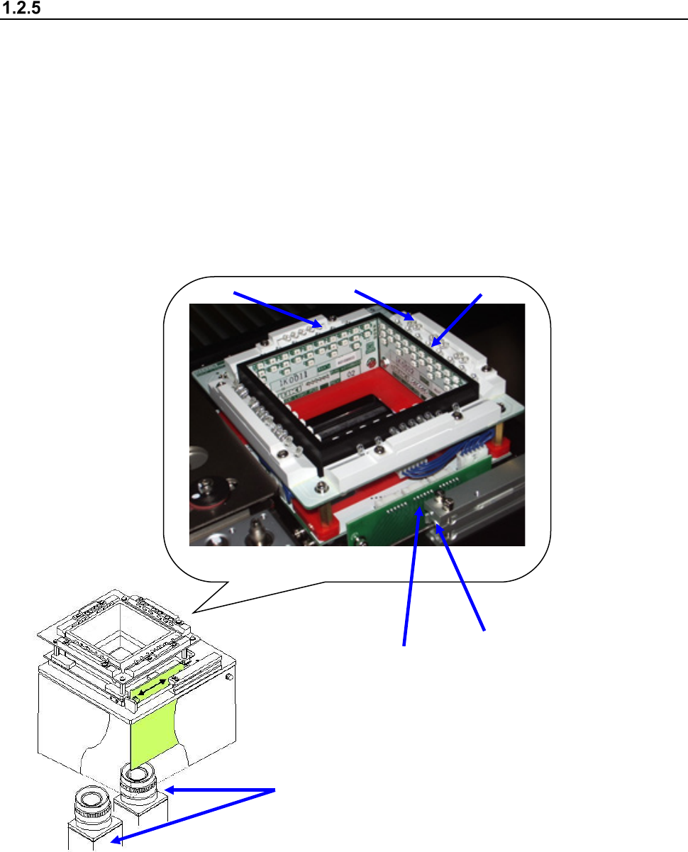
Configuration of a Vision Centering System (VCS)
When the combination and brightness of each LED lighting unit are adjusted, various lighting
patterns are generated and so a lighting pattern suitable for the object of recognition (lead, call, or
component outline) is generated.
The illuminated object of recognition is photographed by the VCS camera provided in the lower part
and then image processing is performed.
Reflective/coaxial lighting : Lead components such as QFP and SOP
Side lighting : Ball components such as BGA and CSP
Penetrative lighting : Outline recognition components
① LED board (for the upper transmittance light)
② LED board (for lower transmittance light)
③ LED board (for the side light)
④ LED board (for the coaxial light)
⑤ 54 mm/27mm/10mm view camera
⑥ Cylinder (Only added when setting 2 cameras)
⑤
③
①
②
④
⑥