RS-1_instruction manual.pdf - 第359页
Part 1 B asic O peration Chapter 4 Cr eating a Produc tion Progra m 4- 24 When you pres s the <Detail Settin gs> button, t he screen like one sho wn below appears. Switch the tabs, “ Mark 1 ,” “Mark 2” and “Mark 3.…
Part 1 Basic Operation Chapter 4 Creating a Production Program
4-23
4.3.3.3 BOC mark
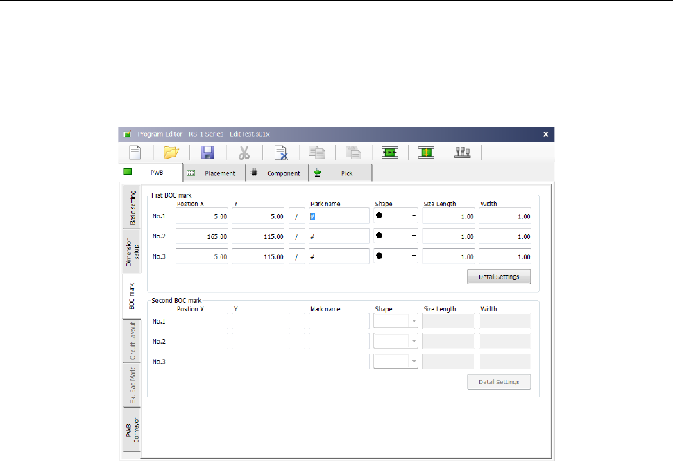
When you select the <PWB mark> button for the menu item “BOC type” on the “Basic setting”
screen, enter the coordinates of a BOC mark viewed from the board reference position in the
“Position X” and “Y” fields of a BOC mark.
When you align the cursor with the XY coordinates, and then press the <Teaching> button
displayed in the operation area on the bottom of the screen, you can invoke the teaching function
and set the XY coordinates with the teaching function also.
(1) Position X, Y
Enter the coordinates of a mark. You have to set two or three BOC marks.
When two BOC marks are used: the system can correct the difference between the
designed dimensions and the actual dimensions (measured dimensions) and the error in
the rotation direction.
Note that if there are two or more marks on a board, select two points located in a
diagonal line of the entire area for placing components.
When three BOC marks are used: In addition to the difference and the error corrected
when two BOC marks are used, the system can correct distortion of the perpendicularity
of the X-axis and that of the Y-axis.
(2) Teaching
The teaching state of a BOC mark is displayed in the field next to the “Position X, Y” fields
(1) above.
“/” indicates the “temporarily completed state,” while “*” indicates the “taught state.”
When you enter the XY coordinates, the “Mark name,” “Shape,” “Size Length” and “Width”
fields are set, and the mark setting is put in the temporarily completed state.
(3) Mark name
Enter a mark name.
(4) Shape
Select the shape of a mark.
(5) Size Length and Width
Enter the size of a mark.
(6) Detail Settings
When you select this button, the “Detail Settings” screen opens.
Part 1 Basic Operation Chapter 4 Creating a Production Program
4-24
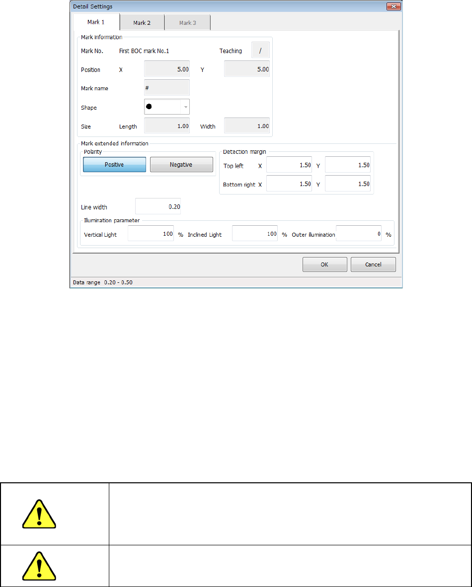
When you press the <Detail Settings> button, the screen like one shown below appears.
Switch the tabs, “Mark 1,” “Mark 2” and “Mark 3.”
(1) Mark information
Information you set on the “BOC mark” screen appears here.
(2) Polarity
Specify whether to reverse the brightness of a shot image.
(3) Line width
Enter the line width of a mark. Note that the value entered here is not used for a shape that
does not require the line width.
(4) Detection margin
Enter the distance from the outer of a mark as the size of the detection frame used to
recognize a mark.
(5) Illumination Parameter
Enter the illumination value to be used when a mark is shot.
CAUTION
If the designed values of mark coordinates are provided (as CAD data),
never teach the X or Y coordinate.
Otherwise, all component placement coordinates will be shifted from the
designed values.
CAUTION
To prevent any accident causing injuries, never put your hand or head
inside the machine during teaching.
Part 1 Basic Operation Chapter 4 Creating a Production Program
4-25
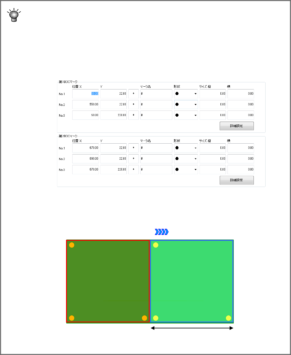
If you use a board whose outer X-dimension exceeds the regulated size (650 mm)
For a board whose outer X-dimension exceeds the regulated size (650 mm), specify a
BOC mark (referred to as the first BOC mark hereinafter) in the range where a
component is to be placed when the board is clamped for the first time and another BOC
mark (referred to as the second BOC mark hereinafter) in the range where a component
is to be placed when the board is clamped for the second time.
Example: For a single-plane PWB that is transferred from left to right and whose size is
900 mm, enter the first BOC mark and the second BOC mark.
Board transport direction
① First component
placement area
② Second
component
placement area
Division position of a long-sized board