RS-1_instruction manual.pdf - 第561页
Part 1 B asic O peration Chapter 4 Cr eating a Produc tion Progra m 4- 226 (8) Checking t he compo nent pick - up position with a ca mera while it is track i ng t he component pick- up height When you pres s the <CAME…
Part 1 Basic Operation Chapter 4 Creating a Production Program
4-225
(5) Displaying the superimpose screen
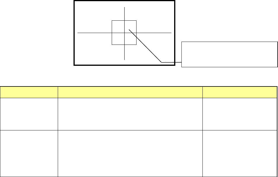
1) Tracking a component pick-up position
When the system is tracking a component pick-up position, it displays the crossed lines
indicating the center of the component pick-up position and the window frame appropriate
for the size and placement angle of a component on the superimpose screen. According to
the setting of the Operation option, the circle whose radius is equal to the length of the
longer side of the component is displayed at the center of the screen.
Display of the center and four corners of a component varies depending on the component
size as described below.
Component size
Four corners of a component
Center of a component
Component whose
shorter side is 4.5
mm or less
The window frame displayed on the screen indicates four
corners of a component.
A placement position whose angle was set is displayed by
rotating the window frame itself.
Center of the point at which
lines are crossed.
Other components
(large components)
The camera moves to each set of coordinates of four
corners: [TOP-L], [TOP-R], [BTM-R] and [BTM-L] in this
order. For a component placement position whose angle
was set, the camera moves to the coordinates obtained by
rotating four corners.
After the camera moves to
all of four corners,
[CENTER] is displayed on
the monitor. The camera
moves to the center of a
component.
(6) Teaching coordinates during tracking
If the tracked coordinates are different from the actual ones, you can teach the component
pick-up coordinates with the teaching function.
<Procedure>
① Move the cursor to the X, Y or Z coordinate.
② Press the <Teaching> button of the function bar to open the “Teaching” screen.
Teach the coordinates and press the <OK> button to obtain the taught coordinates
data.
③ To make the obtained coordinate values valid, press the <OK> button.
To reset the coordinates to the original ones, press the <CANCEL> button.
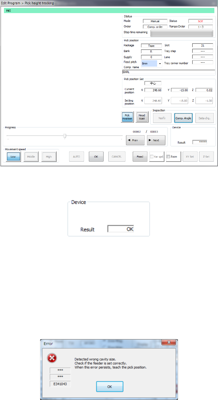
(7) Measuring the component pick-up height with the HMS while the camera is tracking a
component pick-up position
When you press the <HMS> button while the camera is tracking a component pick-up
position, the system can measure the component pick-up height. The “Pick position
tracking” screen is switched to the “Pick height tracking” screen.
The HMS always measures the component pick-up height on the “Pick height tracking”
screen. When the measured value is correct, press the <Z Set> button to reflect it to the
set value.
To return to the tracking operation with a camera, press the <CAMERA> button.
The center of a component or the frame
indicating four corners of the component is
displayed on the screen.
Part 1 Basic Operation Chapter 4 Creating a Production Program
4-226
(8) Checking the component pick-up position with a camera while it is tracking the component
pick-up height
When you press the <CAMERA> button while the camera is racking the component pick-up
height, the system displays the image of the position whose height is being measured. The
screen is switched from the “Pick height tracking” dialog box to the “Pick position tracking”
dialog box.
Although you can change the camera position with operating the touch panel, you cannot
set the XY coordinates of the changed position.
To track the component pick-up height again, press the <HMS> button.
(9) Action to be performed at each point while the machine is tracking the component pick-up
height
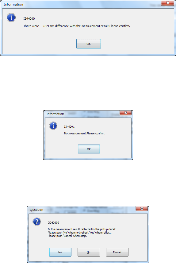
1) When you check the check box "Trace stops if there is a difference of the
measurement value." on the "Pick height tracking" dialog box, the dialog box appears
on the screen as shown in the figure below if the difference is detected. If you select
"Automatic feed" as the "Feed method," the machine stops tracking a pick-up point.
Check the height specified in Pick data.
2) When you check the check box "Trace stops if it is not possible to measure" on the
"Pick height tracking" dialog box, the message appears on the screen as shown in the
figure below if the HMS cannot measure the height. If you select "Automatic feed" as
the "Feed method, "the machine stops tracking a pick-up position. Check the height
specified in Pick data.
3) When you check the check box "The measurement value is taken" on the "Pick height
tracking" dialog box, the dialog box, which asks you whether to save the value
measured by the HMS as the Z coordinate of Pick data, appears on the screen. To
save it, click the <Yes> button.
Part 1 Basic Operation Chapter 4 Creating a Production Program
4-227
(10) Component direction inspection under tracking
While tracking is temporarily stopped, it is possible to execute component direction
inspection.
While the component direction inspection is in process, the following screen is displayed.
After the end of the SOT direction inspection or component direction inspection, the
inspection result is displayed as “OK” or “NG.”
See “(2) SOT Angle” of “(6) Inspection 1” of Section 4.3.5.2 “Creating of component data” of
Chapter 4 for settings of inspection.
(11) Automatic teaching during tracking of a component pick-up position
You can perform the automatic teaching function when the system temporarily stops tracking a
pick-up position.
The system displays the following five error/question dialog boxes during automatic teaching.
1) If the size is greatly different
“Cavity” means a depression in which a component is put.
If the component size is different from the cavity size greatly, the following error message
appears on the screen.