RS-1_instruction manual.pdf - 第30页
Part 1 B asic O peration Chapter 1 Overv iew of the Machine 1- 12 Part na m es of the b ank for the electric tap e feeder Insert t he electric tape f eeder along the ra il guide ① until it is in contact with the fixi n…
Part 1 Basic Operation Chapter 1 Overview of the Machine
1-11
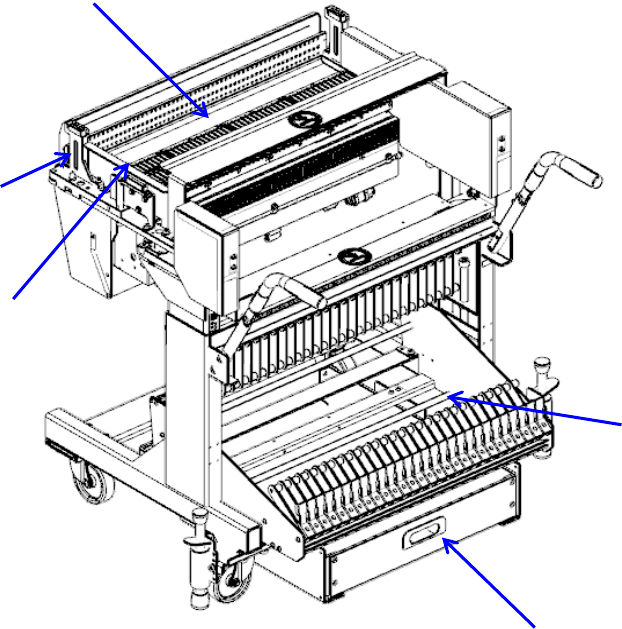
Configuration of the component feeder
Totally two component feeder banks are provided: one bank is located at the front and rear of the
PWB transport unit respectively. The component supply method varies depending on the package
style of components: tape, or tray.
Components fed by a tape (chip components) or those fed in a stick are mounted on the feeder
bank with using a tape feeder, then carried in the main unit.
A tray component is supplied by a tray holder, a matrix tray changer or a matrix tray server.
A tray holder or matrix tray server, can be mounted on the rear of the machine.
Using the Feeder exchange trolley (option), you can attach and detach the feeder bank from the
mounter and make an external setup.
Feeder banks
PWB
Rear
Front
PWB transport unit
* Left to right transport (IN and OUT are inverted for right to left transport)
Part 1 Basic Operation Chapter 1 Overview of the Machine
1-12
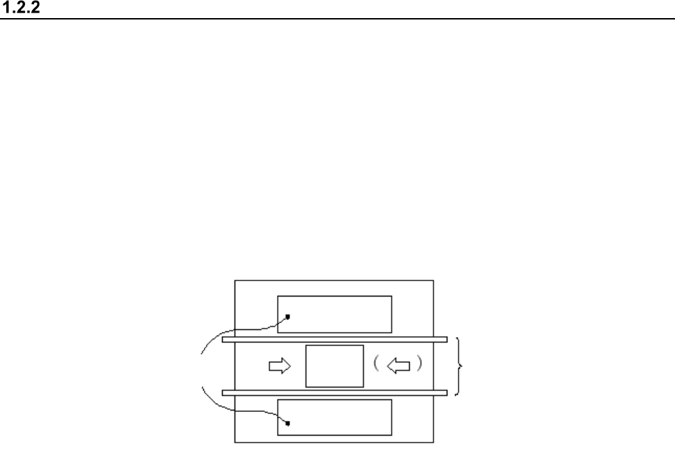
Part names of the bank for the electric tape feeder
Insert the electric tape feeder along the rail guide ① until it is in contact with the fixing block ②
and make the positioning.
Set the electric tape feeder on the bank, seeing the position label ③.
The bank mark ④ is intended to correct the position and posture of the bank.
①
Rail guide ③ Position label ⑤ Locate pin
②
Fixing block ④ Bank mark ⑥ Bank base
④
①
③
⑤
⑥
②
⑤
④
Part 1 Basic Operation Chapter 1 Overview of the Machine
1-13
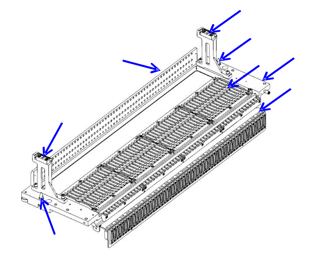
Part names of the overall exchange feeder trolley for the electric tape feeder
Set the tape reel in the reel holder ①.
Raise the E-bank ② and make the positioning with the locate pin ③.
When changing the tape at the setup position, connect the setup connector ④ to the connector on
the ETF side.
Tape reel exchange of RF series electric feeder is done on the set-up stand for electric feeder
(optional).
Carrier tapes, which have been cut during operation of the mounter, accumulate in the trash box ⑤.
①
Reel holder
③
Locate pin
⑤
Trash box
②
E-bank
④
Setup connector
⑤
②
④
③
①