RS-1_instruction manual.pdf - 第55页
Part 1 B asic O peration Chapter 1 Overv iew of the Machine 1- 37 Note 4: Please r efer to f ollowing , rec ognition com ponent si ze of LNC 120 -8 u nit. * For the he ight res triction according to the com ponent s ize,…

Part 1 Basic Operation Chapter 1 Overview of the Machine
1-36
Note 1: When the back light is used to recognize a lead, the lead looks thinner because completely
parallel light is not used.
For some area of the field view, the light illumination from the bottom is used as the back light
with being reflected onto the background plate of the head. Therefore, the lead looks further
narrower when it is positioned in the area lighted with the light from the bottom because the light
is reflected to the lead surface. In some case, the lead cannot be seen at all. As a result,
recognition of a lead with the back light is not guaranteed.
Note 2: The area to be recognized of the maximum-sized component shall be within the field view of □52
mm of a VCS including the component placement position error and a teaching error caused
when the component is picked up.
For the maximum size of the image recognition, the pick-up XY error shall be ±1 mm or less and
the angle error shall be ±3°or less.
When the image recognition applies to components with a size of more than □7 mm, the
components cannot be allocated to adjacent heads.
When a component is recognized with the back light, and the position 1.3 mm or less far from the
edge of the component is picked up, the shadow of a nozzle may prevent the component from
being recognized stably.
Note 3: The pitch of a general-purpose vision component type of lead component (multi connector, etc.)
and ball component that can be recognized in the follows.
Table Standard vision recognition specification
Component type
54mm view
camera
27mm view camera
10mm view camera
Lead
Pitch
0.50 to 22.0mm
0.3 to 11.0mm
0.2 to 0.50mm
Width
0.22 to 10.00mm
0.12 to 5.00mm
0.12 to 1.80mm
Length
0.40 to 10.00mm
0.20 to 5.00mm
0.20 to 1.80mm
Number
1 to 384pcs / 1 element group
Ball
Pitch
1.0 to 22.0mm
0.25 to 11.0mm
0.10 to 4.00mm
Diameter
0.40 to 5.00mm
0.10 to 2.50mm
0.04 to 0.20mm
Number
3 to 6936pcs / 1 element group
Part 1 Basic Operation Chapter 1 Overview of the Machine
1-37
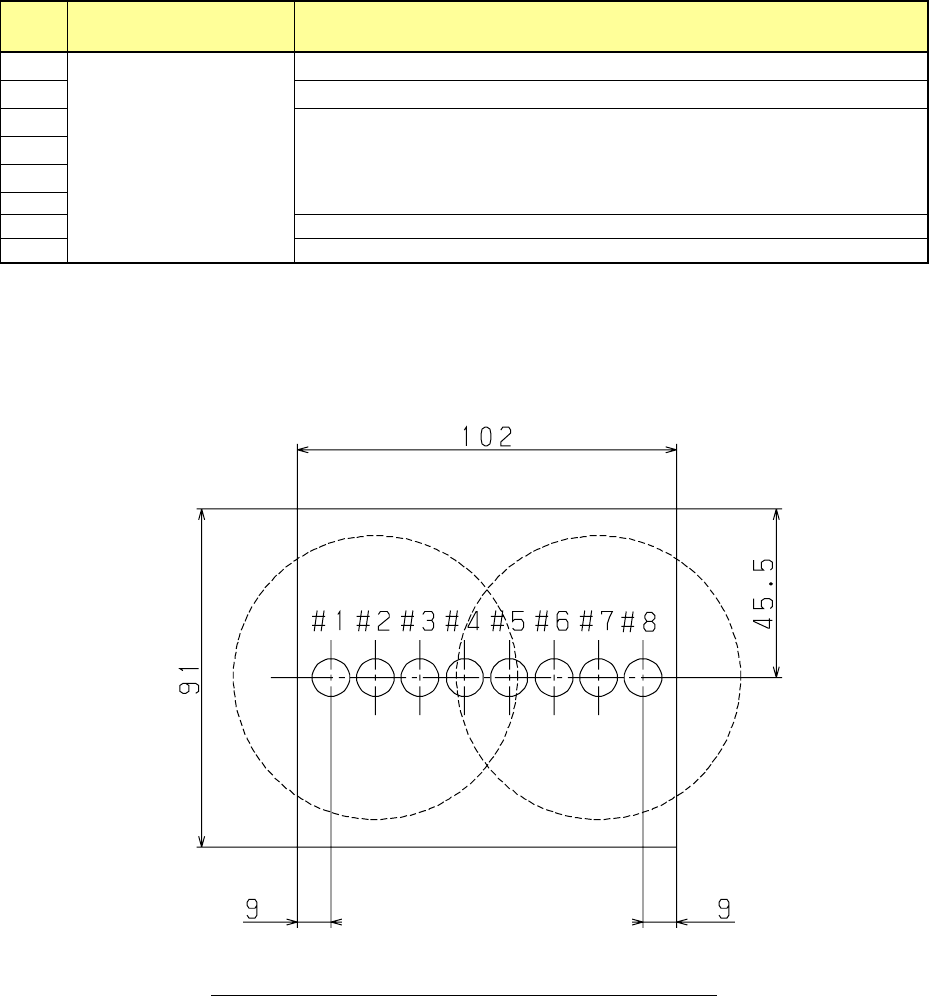
Note 4: Please refer to following, recognition component size of LNC120-8 unit.
* For the height restriction according to the component size, see "(2) Recognition height of laser
recognition component, and (3) Recognition height of image recognition component".
Nozzle
number
Simultaneous measurement
(Up to 8 nozzles)
Applicable maximum component size
1
03015 to □7mm
(Diagonal line length
9.90mm or less)
Up to
□20
mm or a component whose diagonal line length is up to 28.2 mm
2
Up to
□
35mm, or diagonal line 49.5mm
3
Up to □50mm, or diagonal line 70.7mm
4
5
6
7
Up to
□
35mm, or diagonal line 49.5mm
8
Up to
□20
mm or a component whose diagonal line length is up to 28.2 mm
* The maximum component aspect ratio that the LNC 120-8 unit can recognize is up to 60: 1.
* For simultaneous measurement of 4 axes at single axis interval, it is
□
14 mm or 19.8 mm diagonal.
* If a 03015 component cannot be recognized stably due to its shape (for example, if a string art image is
not displayed normally), use a VCS (10-mm field of view camera) (optional).
Fig. Position relations of LNC120-8 and the nozzle
Part 1 Basic Operation Chapter 1 Overview of the Machine
1-38
(2) Component height
The component height specifications of the RS-1/1R differ from those of the conventional
machine.
The height of the placeable component is changed by controlling the LNC120-8 unit position in
the Z-direction.
This shortens the distance between the pickup/placement position and LA surface and achieves
the improvement of the pickup-LA recognition-placement tact.
The position and movement axis of the LNC120 unit are determined to the ZA height and
ZA-axis, respectively.
The ZA height reference is the bottom surface of the LNC120-8 unit.
Additionally, the ZA height is not stepless and is set to several classes as shown below according
to the applicable component height.
Table ZA height classes
Class
Height of applicable component
1 [mm]
More than 0 [mm] and 1 [mm] or less
3 [mm]
3 [mm] or less
6 [mm]
6 [mm] or less
12 [mm]
12 [mm] or less
20 [mm]
20 [mm] or less
25 [mm]
25 [mm] or less
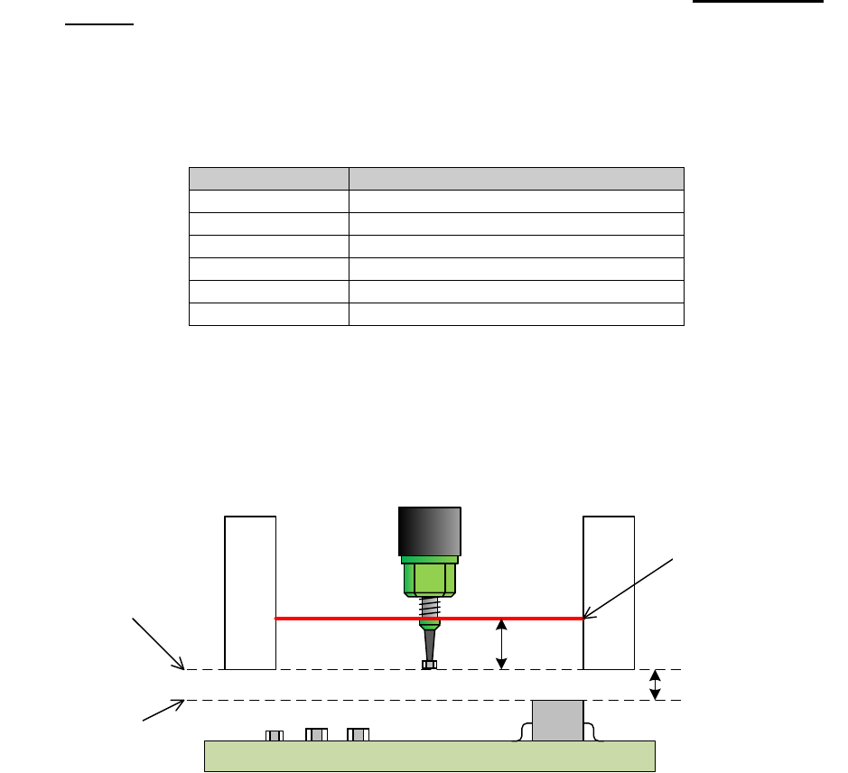
The XY-axis movable height has a margin of 3 [mm] in a class other than 1 [mm] class.
Components applicable to 1mm-class has a margin of 2 [mm].
Additionally, the distance between the bottom of the LNC120-8 unit and the LA surface is 5 [mm]
in each class.
2mmまたは3mm
LNC120下面高さ
XY軸移動可能高さ
搭載済み部品
の最大高さ
レーザ高さ
5mm
Fig. Margin of XY-axis movable height
Placed component
Max. height
Height of bottom surface
of LNC120-8
XY-axis movable height
2mm or 3mm
Laser height