RS-1_instruction manual.pdf - 第1011页
Part 2 D etaile d Descript ion of E ach Functi on Chapter 12 Handling th e Optional Device s 12 - 127 however, set it so that the tag of nozzle face s left side seen fr om the front side of machine to shorten the tag rea…
Part 2 Detailed Description of Each Function Chapter 12 Handling the Optional Devices
12-126
12.17 Individual Nozzle Management System (RFID)
12.17.1 Overview of the function
By recognizing an RFID tag bonded on the side of a nozzle with the antenna when the machine
allocates a nozzle, the machine obtains the RFID (individual management ID) of the nozzle and
associates it with the nozzle operation information to manage nozzles individually.
The purpose of this function is collecting and accumulating nozzle operation information of nozzles
having RFIDs such as the total number of picked components, the total number of components
placed on boards and the number of component pick-up errors continuously to summarize the
information with the production assistance system (JaNets) or the production management system
(IFS-NX).
12.17.2 Device configuration
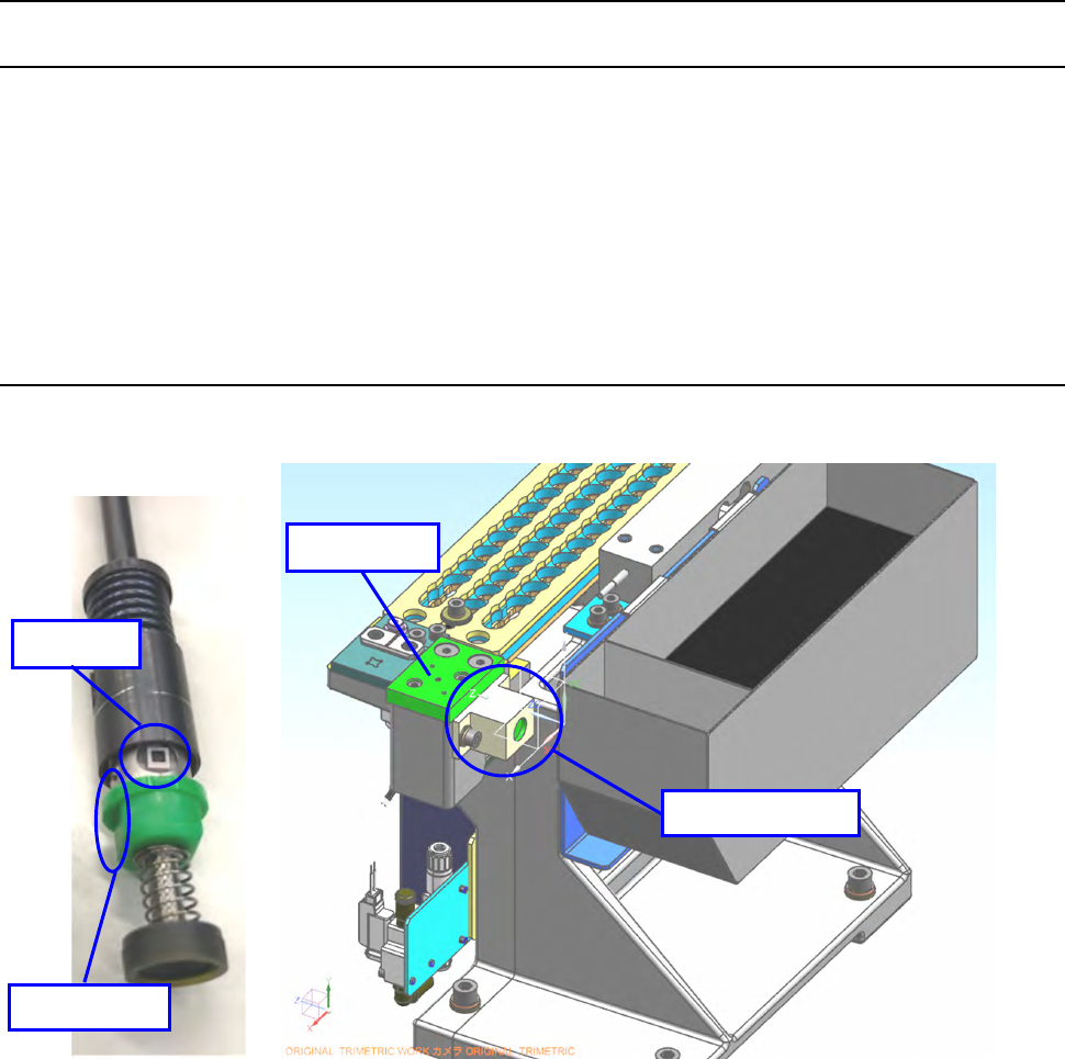
Read the RFID tag pasted on the nozzle with the antenna attached on the side of the CAL block.
* The communication radio wave specification of a nozzle RFID reader (optional) varies depending
on its destination.
Never use it in any area other than the regulated one because such use of the reader violates the
radio wave law.
Nozzle RFID readers for an RS-1R are designed for the following destinations.
- 40214759 NOZZLE RFID READER_ASM_Japan (for Japan)
- 40218744 NOZZLE RFID READER_ASM_China (for China)
- 40218745 NOZZLE RFID READER_ASM_USA (for the U.S.A.)
- 40218746 NOZZLE RFID READER_ASM_Europe (for the EU)
* The factory shipment option is not set for the nozzle RFID reader (optional). All options are
assembled at the installation.
* When the nozzle is set on ATC, the tag of standard nozzle can face both of right and left sides,
RFID tag
D-cut side
RFID antenna
CAL block
Part 2 Detailed Description of Each Function Chapter 12 Handling the Optional Devices
12-127
however, set it so that the tag of nozzle faces left side seen from the front side of machine to
shorten the tag reading time.
The tag of large nozzle can face both of front and rear sides, however, set it so that the tag of
nozzle faces the front side seen from the front side of machine to shorten the tag reading time.
12.17.3 Procedure for reading an RFID
An RFID is to be read when you allocate nozzles. See Section 8.3.2.3 “Nozzle setup” for allocation
of nozzles.
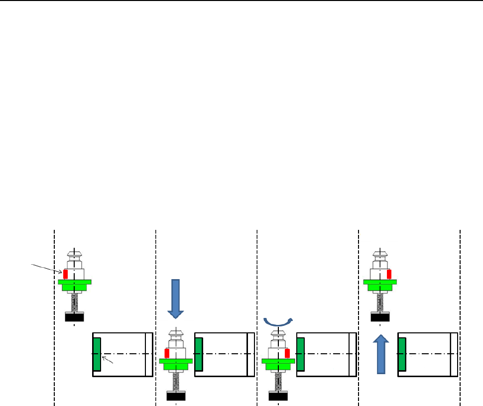
An RFID is read in the following order after the corresponding nozzle is allocated.
* Any RFID of a nozzle is not read during production.
① A nozzle is attached.
② The head moves to a position above the RFID tag recognition position.
③ The head moves down to the RFID recognition height to recognize the RFID.
④ If the head cannot recognize the RFID, it recognizes the RFID again after rotating the nozzle by
180 degrees.
⑤ After recognizing the RFID, the Z-axis of the head moves up.
⑥ The nozzle is returned to the original position.
① ② ③ ④ ⑤ ⑥
RFID tag
Antenna
Part 2 Detailed Description of Each Function Chapter 12 Handling the Optional Devices
12-128
12.17.4 Machine Setup
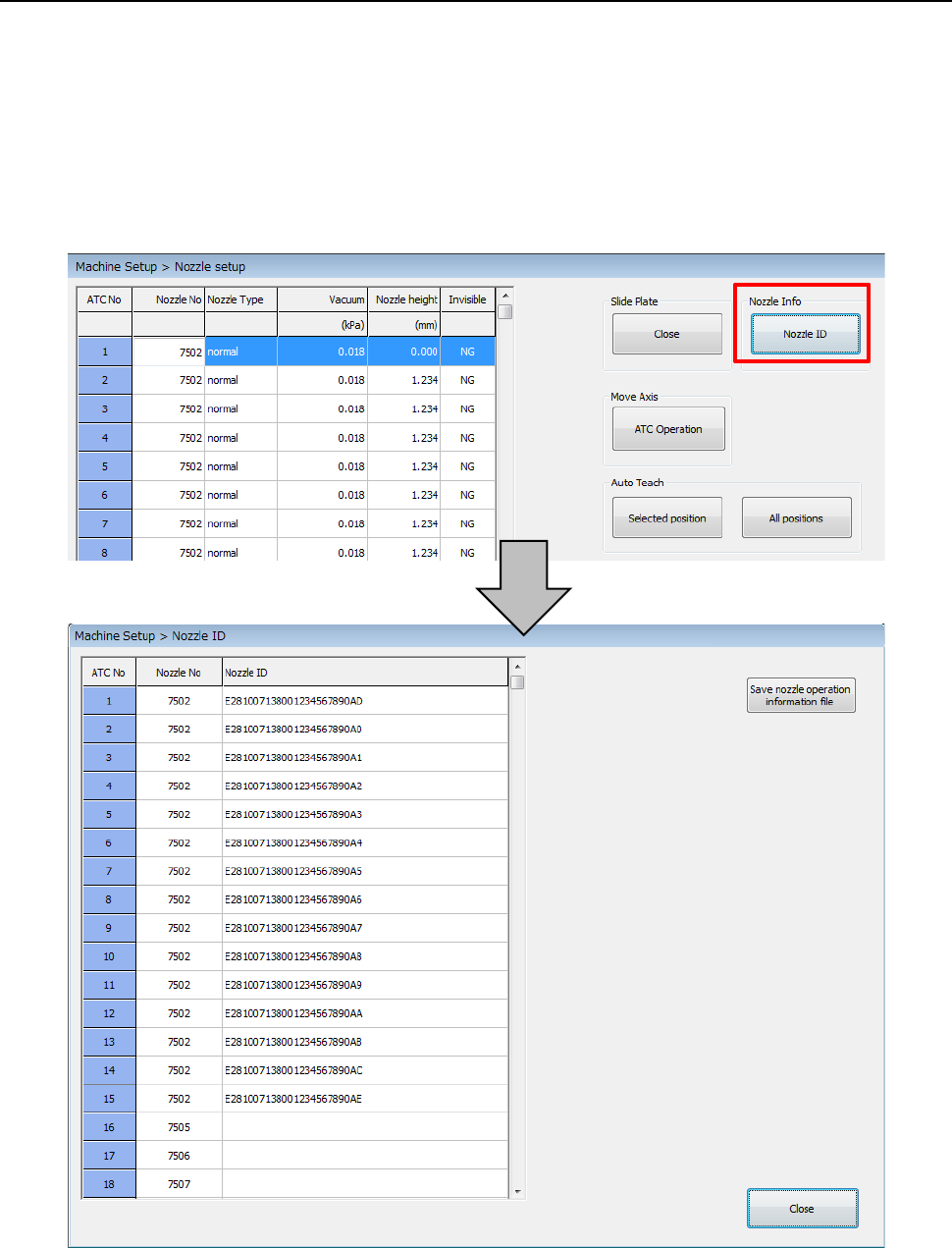
Select the commands [Setting] – [Machine Setup] from the menu to open the “Machine Setup”
screen. Select the commands [Nozzle] – [Nozzle setup], and then allocate the selected nozzle(s)
or automatically allocate nozzles. After nozzles are allocated, the corresponding RFIDs are read.
You can check the nozzle allocated to each ATC hole and the corresponding RFID on the nozzle
information dialog box displayed when you press the <Nozzle ID> button.
When you press the <Save nozzle operation information file> button on the “Nozzle ID” dialog box,
you can display the dialog box for saving a nozzle operation information file on the screen. (See
Section 1.9.6 “Get and Save Machine Data.”)