RS-1_instruction manual.pdf - 第720页
Part 2 D etaile d Descript ion of E ach Functi on Chapter 8 Machine Set up 8- 12 VCS W hen yo u sel ec t “ VCS, ” the following s creen ap pears. When you clic k each ta b, you can spec ify each of “ Head, ” “ Base, ” “ …
Part 2 Detailed Description of Each Function Chapter 8 Machine Setup
8-11
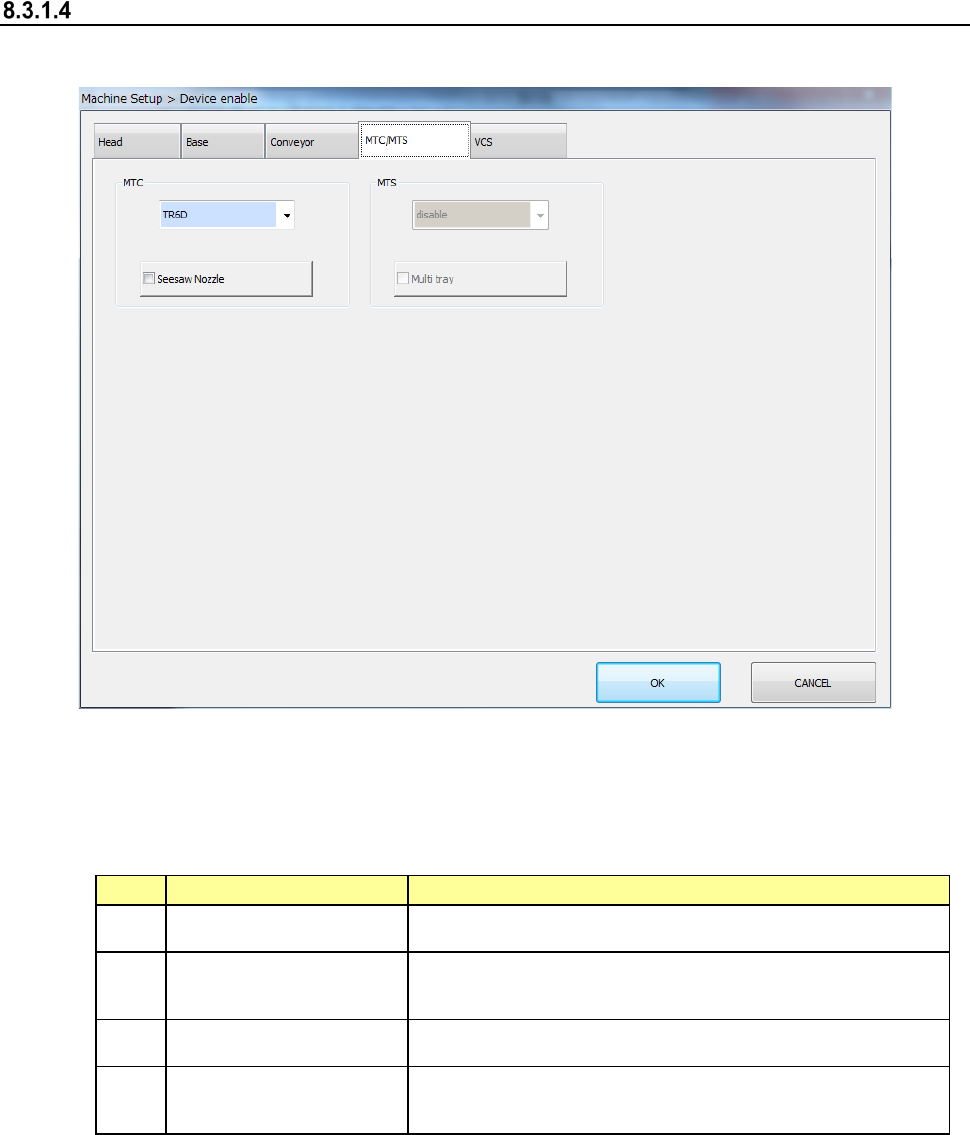
MTC/MTS
When you select “MTC/MTS,” the following screen appears.
When you click each tab, you can specify each of “Head,” “Base,” “Conveyor,” “MTS” and “VCS.”
(1) Setting items
The use setting of MTS is performed.
No.
Item
Description
1 MTC Set the use/no use of the unit and its type.
2 Seesaw Nozzle
When MTC is not unused, this item can be set.
Set whether to use a seesaw nozzle or not.
3 MTS Set the use/no use of the unit and its type.
4 Multi-tray
When MTS is not unused, this item can be set.
Set the use/no use of the multi-tray.
(2) How to set
1) Select a model name in the combo box.
2) Specify the Use/No use of the multi-tray by check button.
When a check mark is attached, this means a “Use” setting. If no check mark is
attached, this means a “No use” setting.
Part 2 Detailed Description of Each Function Chapter 8 Machine Setup
8-12
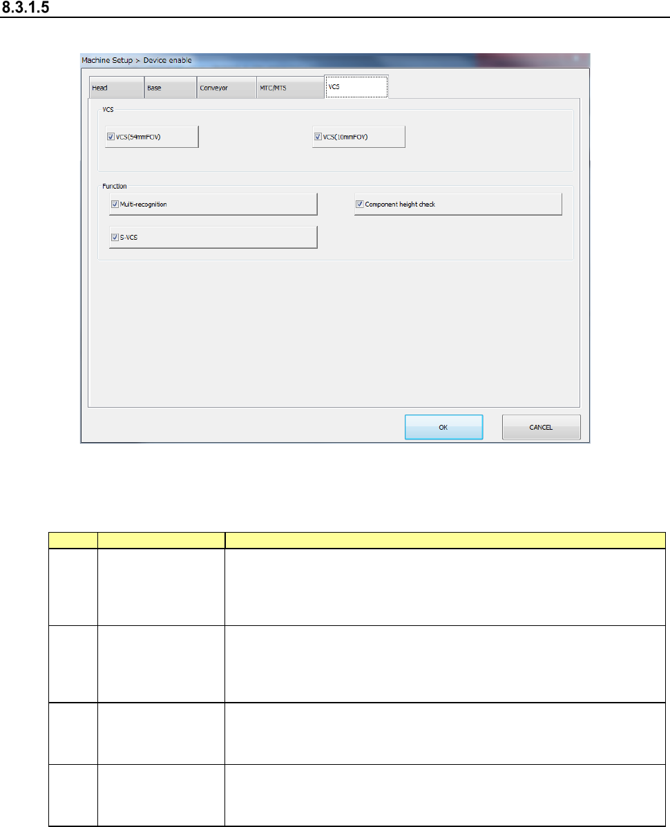
VCS
When you select “VCS,” the following screen appears.
When you click each tab, you can specify each of “Head,” “Base,” “Conveyor,” “MTS” and “VCS.”
(1) Setting item
The use setting of VCS is performed.
No.
Item
Description
1
Device enable
(VCS)
If the VCS should happen to break down, this item directs that this unit not
be used so that pick-placing can be performed without changes to the
production program.
In the case of a “No use” setting, the placement of VCS recognition
components is skipped.
2 Multi-recognition
Specify whether to use multi-recognition or not. If you set multi-recognition
not to be used without checking this check box, the machine does not
recognize a component in Non-stop mode (that is, the machine recognizes
a component in a normal way) even though multi-recognition is set to be
used with a production program.
3
Component height
check
Specify whether to check the component height when multi-recognition is
set to be performed. If you set the component height check not to be used
without checking this check box, the machine does not check the component
height during multi-recognition.
4 S-VCS
Specify whether to use an S-VCS or not. If you set an S-VCS not to be
used without checking this check box, the machine stops to recognize a
component even though an “S-VCS” is set to be used in the corresponding
production program data.
(2) How to set
1) Mark the check box to enable the device unit.
A check mark activates the setting while a blank deactivates it.
Part 2 Detailed Description of Each Function Chapter 8 Machine Setup
8-13
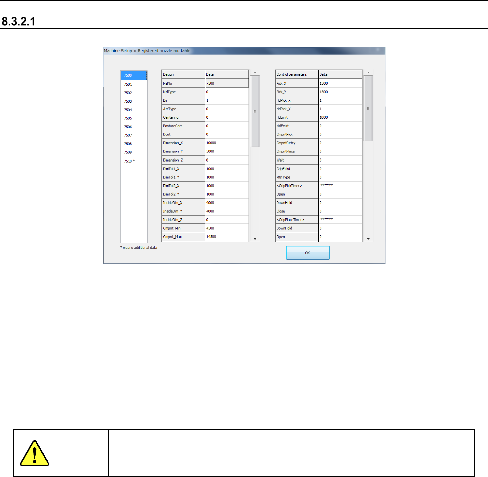
8.3.2 Nozzle
Registered nzl. No. table
When you select “Registered nzl. No. table”, the following screen appears.
The list of nozzle numbers of the nozzle information registered at the present appears in the left
list box.
If any customized nozzle is not registered, only the standard nozzles (whose number is 7500 to
7509) are displayed here.
- Data corresponding to the nozzle number displayed in this list of nozzle numbers is
displayed in the right nozzle information table.
When you change the selected nozzle number to another one, the corresponding nozzle
information appears here simultaneously.
- The left side indicates the “designated values,” while the right side indicates the “Control
parameter information.” They fully correspond to the entry name in the file format
(NZL*.INI) when the nozzle information is read.
CAUTION
Never change the settings displayed here. If you happen to change one of
them, the system may not place a component on a board normally. If you
have to change any setting, contact our technical person.
Nozzle information editing function
Step 1
When you click “Design value information” or the line of control parameter window, the
design value information of the corresponding line or the data of control parameters is
put in an editing status. However, it is impossible to edit nozzle No. (Nzl. No.) and non-
editing field (data without display data).
Step 2
After editing, the data on the screen is updated by pressing the [Return] key. In the
case of a parameter error at a return, the data just before editing is displayed again.
When you click the nozzle information window at editing or scroll the window by clicking
the vertical scroll bar, edit processing is cancelled.
Step 3
After editing is performed, the <Cancel> button is displayed on the screen. When you
press the <Cancel> button, all the edited contents are cancelled.
If an input range error is caused by pressing the <OK> button, they are also cancelled.