RS-1_instruction manual.pdf - 第457页
Part 1 B asic O peration Chapter 4 Cr eating a Produc tion Progra m 4- 122 4.3.6 .2 Creating Pick data (1) A ngl e Specify the com ponent picking ang l e. When “Auto” is selected f or the menu item “Side,” yo u do not ha…

Part 1 Basic Operation Chapter 4 Creating a Production Program
4-121
The range of slots of a feeder bank to be occupied varies depending on the tape widths and the
tape feeder models.
* To attach an EF series electric feeder on the machine, you have to install the RF-ETF
attachment on it.
Tape
width
Number of feeders
that can be
attached on the RF
bank
Number of feeders
that can be attached
on the RF/EF bank
Maximum number of
feeders that can be
attached on the bank
Number of
occupied slots
RF
EF
RF
EF
RF
EF
RF
EF
4 mm
56
-
56
-
112
-
1
-
8 mm
56
-
56
28
112
56
1
2
12 mm
28
-
28
28
56
56
2
2
16 mm
28
-
28
18
56
36
2
3
24 mm
18
-
18
18
36
36
3
3
32 mm
14
-
14
14
28
28
4
4
44 mm
11
-
11
11
22
22
5
5
56 mm
9
-
9
9
18
18
6
6
72 mm
6
-
6
-
12
-
9
-
88 mm
5
-
5
-
10
-
10
-
Part 1 Basic Operation Chapter 4 Creating a Production Program
4-122
4.3.6.2 Creating Pick data
(1) Angle
Specify the component picking angle.
When “Auto” is selected for the menu item “Side,” you do not have to enter this item. In this case,
“*” is displayed on the “List” screen, while this menu item itself is dimmed on the “Form” screen.
When “Front” or “Rear” is selected for the menu item “Side” and some value is specified in the
“Position” field, you can change the value already set for this item. The angle set on the
"Component" data screen is set here by default.
To change the value, move the input focus to the “Angle” field, and then enter the desired value.
Even though you enter a value into this “Angle” field on the “Pick” data screen, the
corresponding angle is not changed on the “Component” data screen or database.
(2) Side
Specify on which side to set a feeder, on the front side or on the rear side.
“Auto” is selected in this field as the initial value.
When “Auto” is selected, the Optimization function assigns a feeder.
Auto
The Optimization function assigns a feeder.
Front
Components are supplied on the front bank.
Rear
Components are supplied on the rear bank
When “Tray” is selected as the “Package,” you cannot select “Front.”
To assign an electric feeder (EF) to the machine, you have to select the side on which the electric
bank (RF/EF) is attached.
You have to specify this “Side” menu item together with the next item “Position.”
When you select two or more pick data records to change the setting of the menu item “Side,” you
can select “Auto” only.
8mm-width-1mm-feed pitch and 12mm-2mm-feed pitch can be selected only for the electric feeder
(RF).
To use the electric feeder (EF) for the electric bank (RF), an attachment (option) is needed.
(3) Position
Enter the position for mounting a component supply unit.
Component supply unit Number to be specified
Tape feeder
Stick feeder
Number of a feeder mounting hole to which the fixing pin at the front-end of the
machine is inserted.
Tray holder Number of a feeder mounting hole indicated with the mounting marker of a tray
holder
DTS/MTC/MTS Number of the level on which a tray is stored
You cannot specify another type of component supply unit on the position whose
number was already specified for one type of component supply unit.
Example: If you specify “Front 10” in this field for an RF 12-mm tape feeder, you
cannot specify any other feeder at the positions from Front 10 to 11.
Part 1 Basic Operation Chapter 4 Creating a Production Program
4-123
(4) Lane
When you use a stick feeder, select the lane number.
The lane numbers are assigned from 1 when viewed from the left on both the front side and the
rear side.
Only one lane is to be used on the current supply device.
When you use a DTS, select the stage on which a tray component is stored.
The system automatically calculates the component pick-up position from the DTS based on the
tray information of the Component data to show it.
The top side is the first stage, while the bottom side is the second stage.
(5) Feeder type (You have to specify this menu item for a tray, an electric tape feeder or a stick
feeder.)
Select a type of a tray an electric tape feeder or a stick feeder.
Note that the contents set in the component data of a stick feeder or a tray are displayed here. To
change any of the contents, do it on the “Component” data screen.
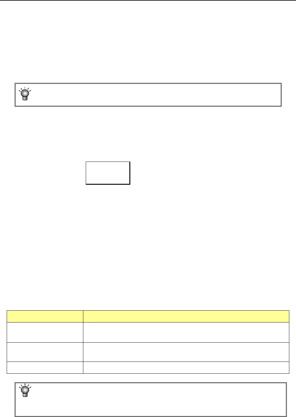
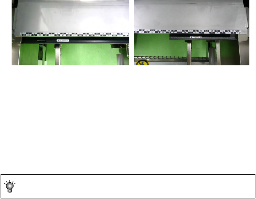
• Tray holder
Tray holders are classified into "Type 1 (full specification)" and "Type 2 (half specification)."
Tray holder (Type 1) Tray holder (Type 2)
* When installing a tray holder, check it at the position of the ▲POSITION mark.
● For electric bank (RF) :
When the electric bank (RF) is used, only the electric tape feeder (RF) can be selected for
the feeder type.
● For electric bank (RF/EF) :
When the electric bank (RF/EF) is used, the electric tape feeder (RF) or electric tape feeder
(EF) can be selected for the feeder type. The default setting is the electric tape feeder (RF).
To mount the electric tape feeder (EF), an optional attachment is needed.
When the electric feeder (EF) is mounted on the electric bank (RF/EF) using the
attachment, the pickup accuracy is not guaranteed.