RS-1_instruction manual.pdf - 第550页
Part 1 B asic O peration Chapter 4 Cr eating a Produc tion Progra m 4- 215 (3) While the camera is t racking a comp onent pla cement position After a compo nent placement position i s tracke d, or while each comp onent p…
Part 1 Basic Operation Chapter 4 Creating a Production Program
4-214
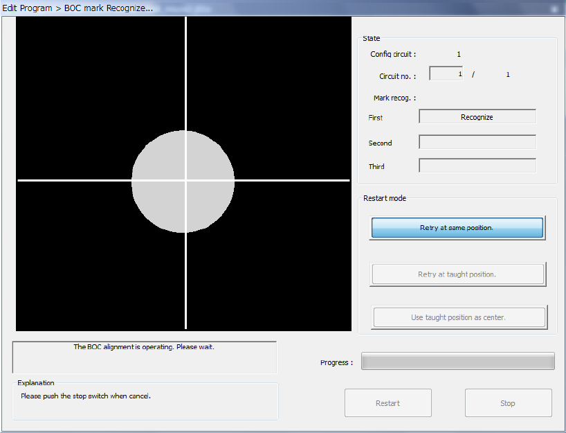
(2) Executing the BOC alignment operation
Immediately after the camera starts tracking a component placement position, the system
executes BOC alignment operation to improve the precision of the component placement position
if a production program on which a BOC mark is set is used. (BOC marks of all circuits are to be
recognized.)
Part 1 Basic Operation Chapter 4 Creating a Production Program
4-215
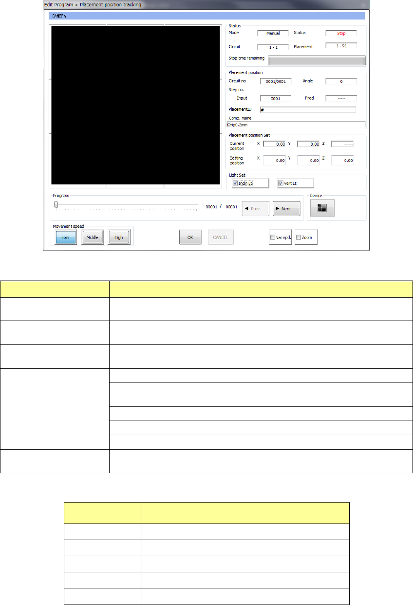
(3) While the camera is tracking a component placement position
After a component placement position is tracked, or while each component placement coordinate
is being tracked, the following dialog box appears.
1) Status
Menu item
Overview
Mode
The feeding method specified with the menu item “Feed method,”
“Auto” or “Manual,” is displayed here.
Circuit
The range of circuits to which placement tracking is to be
conducted is displayed here.
Placement
The range of component placement positions to which placement
tracking is to be conducted is displayed here.
Status
“Moving” indicates that the axis is moving.
“Pause” indicates that the axis stops temporarily in Automatic Feed
mode.
“Stop” indicates that the axis stops manually or intentionally.
“Axis esc” indicates that the axis is moving to the safety position.
“Mark recog” indicates that the system is recognizing an IC mark.
Stop time remaining
The progress bar shows the remaining stop time in Automatic Feed
mode.
2) Placement position
Menu item Overview
Circuit no Circuit being measured/Total number of circuits
Angle Component placement angle being measured
Step no. Placement data number being measured
Placement ID Placement ID being measured
Comp. name Name of a component being measured
Part 1 Basic Operation Chapter 4 Creating a Production Program
4-216
3) Light Set
Select an OCC lighting type to be turned on.
You can select [Incin Lt] [Vert Lt] or [OuterRing].
The [outer ring] button is displayed only when "Solder print recognition placement position
correction (option)" is set.
4) Placement position Set
The “Current position” indicates the coordinates of the component position being tracked.
The “Setting position” indicates the coordinates of the component placement position set
with the production program.
You can manually enter or teach the coordinates of the component placement position
shown in the “Setting position” column to change them.
5) Var spd.
When you check off the [Var spd.] check button, the axis moving speed is increased if you
continue to press the Move button continuously at teaching.
6) Zoom
When you check the <Zoom> check button, you can enlarge the image shot with the camera
and superimposed on the screen if you enable the option “Enable digital zoom teaching” on
the “Operation option” screen.
When the length of the longer side of the component outer dimensions is 2.26 mm or more,
the system does not enlarge any image shot with a camera regardless of the setting of the
“Operation option” screen.
When “the placement angle” + “the circuit angle” is not any of 0, 90, 180 and 270 degrees,
the system does not enlarge any image. The system switches the enlargement factors as
shown below depending on the outer dimensions of a component:
• 4x zoom (The option “Enable 4× zoom” has to be checked on the “Operation option”
screen.)
When the length of the longer side of a component is from 1.11 mm to 2.25 mm: the
displayed image is doubled in size.
When the dimension of the longer side is from 0.01 mm to 1.10 mm, the displayed image
is quadrupled in size.
• Without 4x zoom
When the length of the longer side of a component is from 0.01 mm to 2.25 mm, the
displayed image is doubled in size.
7) OK/CANCEL
These buttons are enabled only after you manually enter coordinates or change them by
teaching operation.
When you press the <OK> button, XY coordinates are applied to the placement data.
If you do not want to apply the changed value, press the <Cancel> button.
If the coordinates are already shifted by teaching when the <Cancel> button is pressed, the
coordinates are returned to the original position.
8) Progress
The progress bar advances one by one according to the position to be tracked. When you
move this progress bar while the system is stopping, you can move the camera to the
previous point or the next point. When you press the <Prev> button, the camera moves
back to the previous component pick-up position. When you press the <Next> button, the
camera moves to the next component pick-up position.