RS-1_instruction manual.pdf - 第136页
Part 1 B asic O peration Chapter 2 Pr oduction 2- 25 Adjusting the PWB transport rail width <How to adjust ment the rail width on t he “Autom atic conve yor width a djustm ent” screen> (1) Select the “Product ” but…
Part 1 Basic Operation Chapter 2 Production
2-24
<Overview of the PWB transport unit construction>
Attach the conveyor stoppers on the right side when the PWB feeding direction is L to R; attach
them on the left side when the PWB feeding direction is R to L. When conveyor stoppers are used,
the PWB is clamped at the position where the front end of the PWB comes in contact with the
conveyor stopper on the downstream (i.e. OUT) side.
1) When a board is loaded to the machine, and the IN sensor ① detects it, the conveyor motor
⑩ drives the drive shaft ⑪ to cause the conveyor belt to start transporting it. Additionally, the
stopper 19 turns ON at the same time.
2) When the PWB reaches the stopper 19, the STOP sensor 18 detects it and the support tables
13 and 14 move up. At this time, the outer shape of the PWB is fixed by the stopper 19 and
support pin. After the PWB has been fixed temporarily, the stopper 19 turns OFF to finish fixing
the PWB.
3) After the PWB has been fixed, the next PWB is carried in in the same manner and it waits at the
position of the WAIT sensor 3.
4) When the system finishes producing a PWB, the fixed board (PWB) starts being ejected.
5) When the first PWB passes through the C-OUT sensor 5, the stopper 19 turns ON again to
make the preparations for fixing the next PWB.
Part 1 Basic Operation Chapter 2 Production
2-25
Adjusting the PWB transport rail width
<How to adjustment the rail width on the “Automatic conveyor width adjustment” screen>
(1) Select the “Product” button from the main menu, the [Support] command, and then the [Plan
support] command.
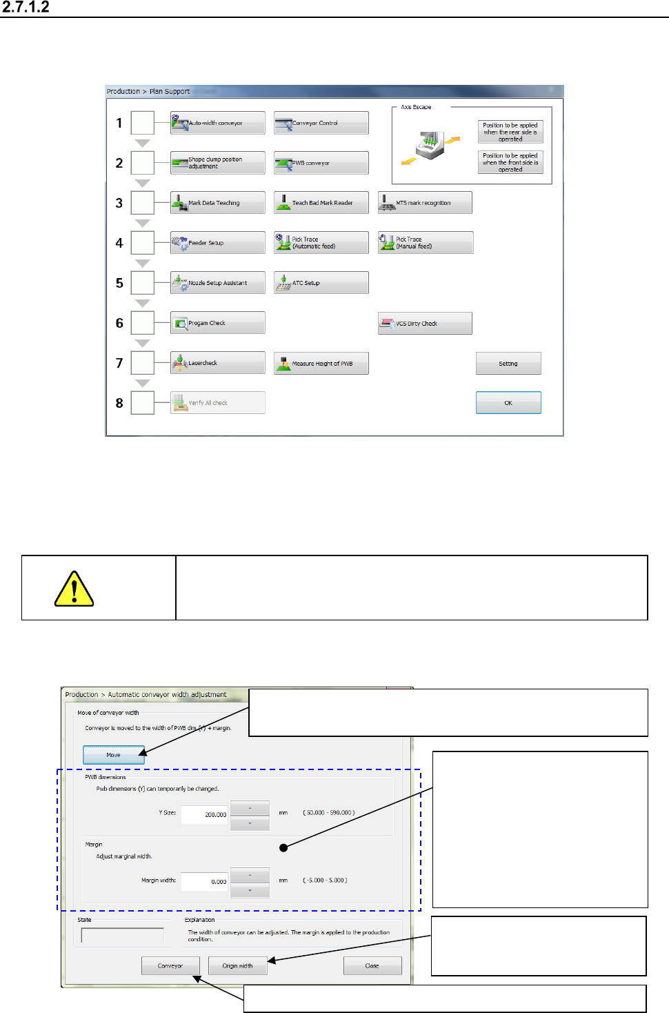
(2) Adjust the conveyor width.
When you press the <Auto-width conveyor> button, the “Automatic conveyor width adjustment”
screen appears.
The operation for “Automatic board width adjustment” varies depending on the conveyor lane
configuration, a single-lane conveyor or a dual-lane conveyor.
CAUTION
When you click the <Move> button with following the instruction below,
the conveyor starts operating. Before clicking this button, be sure to
check to see if there is no obstacle in the conveyor movable section.
1) Automatic board width adjustment
③ Select the <Move> button to adjust the conveyor width.
The motor rotates and the machine adjusts the conveyor width.
④ Check to see if a PWB is transported with the conveyor smoothly.
②
Enter the desired value into the
“Y Size” field and the “Margin
width” field respectively.
(If the conveyor width is not
appropriate for a board to be
transported, be sure to enter
the appropriate value into the
“Margin width” (the allowable
input value range: from - 0.5
mm to 0.5 mm).
①
Select the <Origin width>
button to return the conveyor to
its origin.
Part 1 Basic Operation Chapter 2 Production
2-26
Adjusting the shape clamp reference
<How to change the position>
(1) Select the “Product” button from the main menu, the [Support] command, and then the [Plan
support] command.
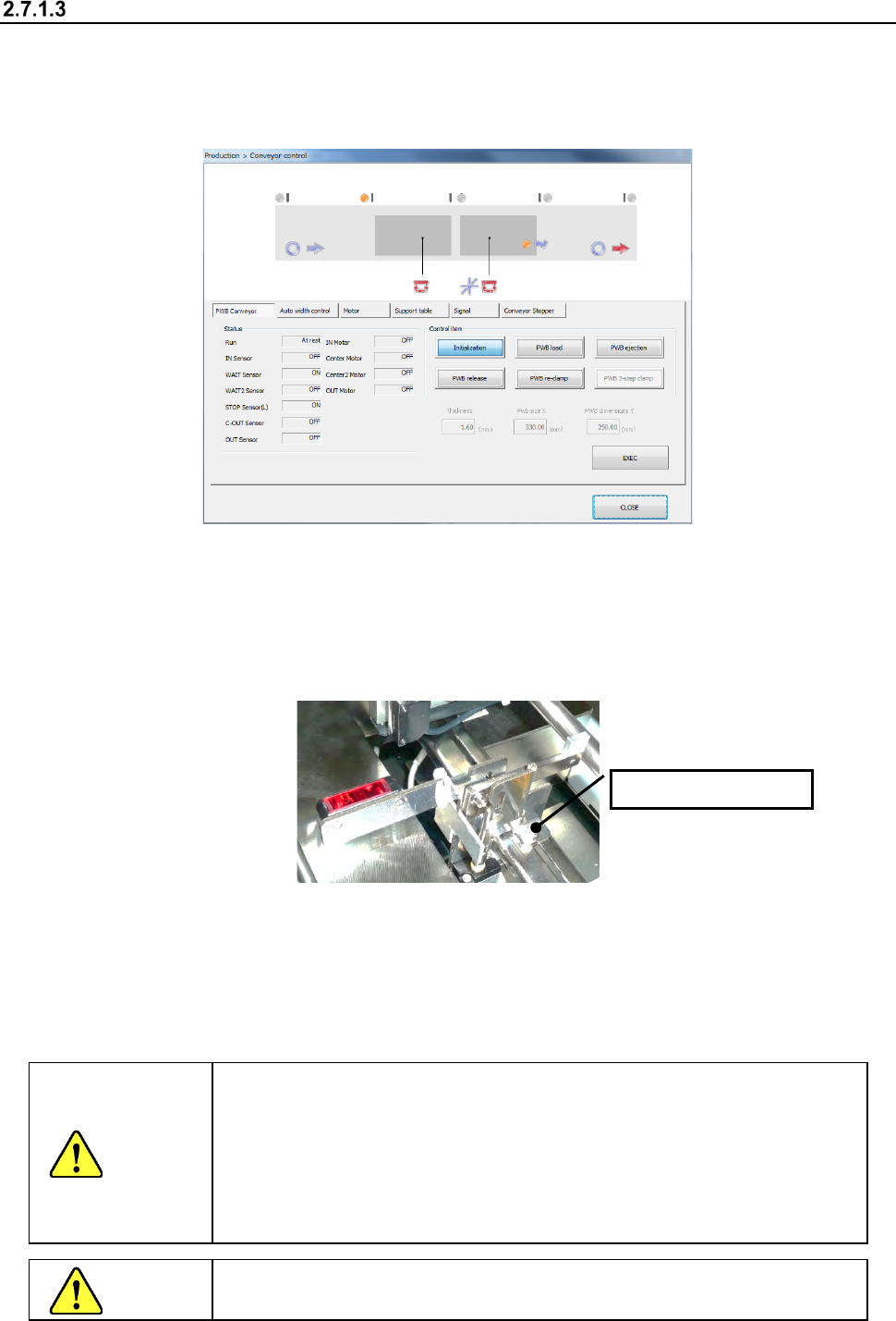
When you press the <Conveyor control> button, the “Conveyor control” screen appears.
(2) Turn the stopper ON.
Select “Conveyor Stopper” and press the <ON> button.
(3) Push the PWB to be produced until it comes in contact with the stopper.
If the PWB has a notch, etc. at the contact point and the contact status is unstable, make
adjustment by loosening the two screws at the root of the stopper and moving the stopper by
hand.
(4) Arrange the support pins.
Place the support pins on the support table suitably according to the PWB to be produced. Placing
support pins under a QFP and other components which require high precision of placement
improves the precision.
(5) After adjustment, press the <CLOSE> button on the “Conveyor control” screen to finish
conveyor control.
CAUTION
The shape clamp reference position is the origin (i.e. a reference point) of
the PWB coordinates of the program data.
Consequently, when the stopper position has been adjusted, make sure
to reset it following Section 2.7.1.4 “Adjusting the shape clamp reference
position”.
The PWB origin can be changed by the “PWB data” in the production
program. (See Section 4.3.3. “PWB data” of Chapter 4).
CAUTION
While the machine is operating, NEVER insert your hand, head, etc.
inside the machine.
Loosen the screw.