RS-1_instruction manual.pdf - 第42页
Part 1 B asic O peration Chapter 1 Overv iew of the Machine 1- 24 Comp onent pl acem ent a ccuracy XY (when a co mponent i s recogni zed with a V CS) Unit: μ m Component ty pe Recognition w ith a VCS Remarks Aluminum el …
Part 1 Basic Operation Chapter 1 Overview of the Machine
1-23
Placement accuracy
(1) Placement accuracy (X, Y)
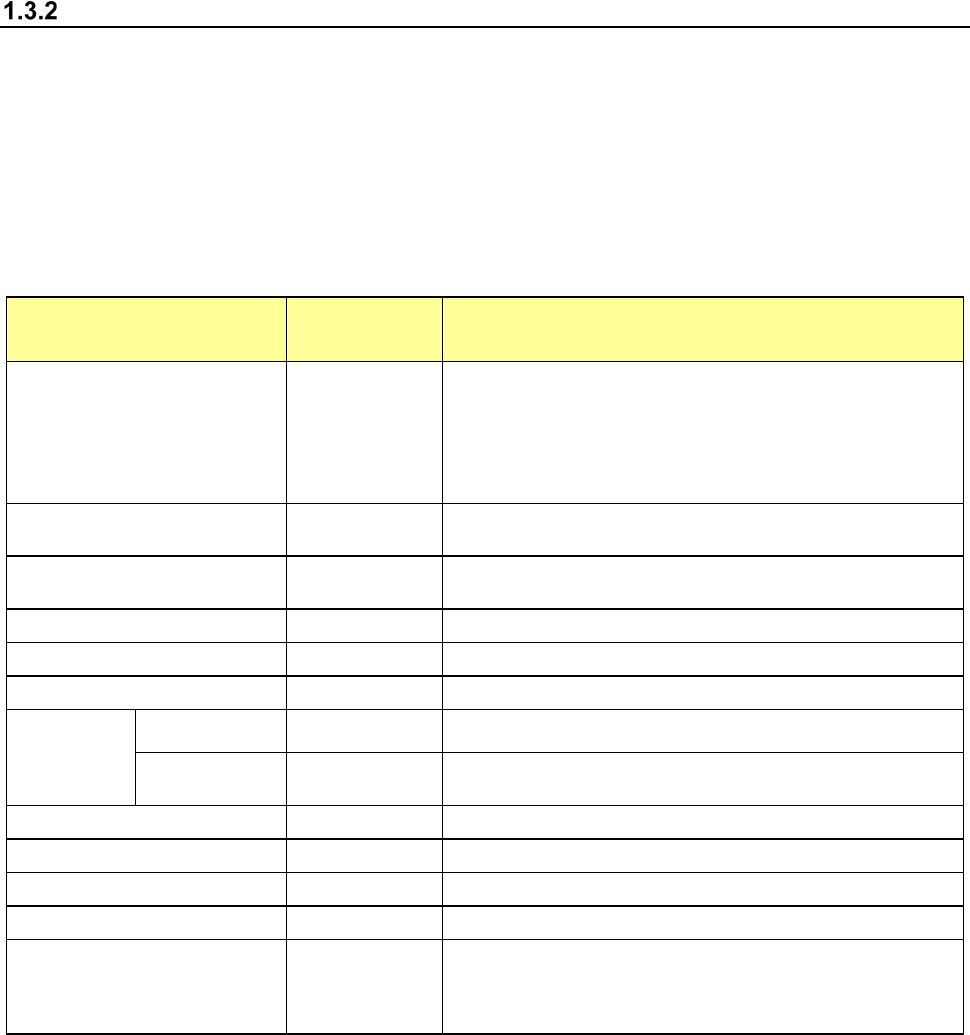
The following table lists the placement accuracy data for different types of components.
A poorer accuracy than the value described below results depending on the components that
may have an edge or plastic mold burrs at the area detected with the laser align function, and
that may have a moving part to be detected with respect to the pick port.
Component placement accuracy XY
(when a component is recognized with laser or board reference mark)
Unit: μm
Component type LNC120-8 Remarks
Square chip 03015, 0402
± 35
When the speed for moving down to place a component on a
board is set to “Slow 2”
Note: If a 03015 component cannot be recognized with laser
stably due to its shape (for example, if a string art image is not
displayed normally), use a VCS (10-mm field of view camera)
(optional).
Square chip 0603, 1005, 1608 or
more
± 50
Square chip (LED)
± 50
The placement accuracy of a square chip LED component shall
be attained when it can be recognized
MELF
± 100
SOT
± 150
See Note 2
Aluminum electrolytic capacitor
± 300
SOP, TSOP
Burr on one side
150 μm or less
± 150
See Note 3
In the direction
parallel to a lead
± 200
This accuracy shall be measured at the cross-section
measured with laser.
PLCC, DOJ
± 200
QFP,(Pitch: 0.8 or more)
± 100
See Note 3
QFP,(Pitch: 0.65)
± 50
See Note 3
BGA
± 100
Other large components
± 300
The accuracy obtained when the component placement
position is corrected according to the recognized component
image shall be an absolute value from a component reference
mark or a board reference mark.
Part 1 Basic Operation Chapter 1 Overview of the Machine
1-24
Component placement accuracy XY (when a component is recognized with a VCS)
Unit: μm
Component type
Recognition with a VCS
Remarks
Aluminum electrolytic capacitor
±150
S OP,
TSOP
Right angles to a lead
±80
Direction parallel to a lead
±120
See Note 3
PLCC, SOJ
±80
QFP(Pitch: 0.65 or more)
±40
Component whose
image is to be divided
for recognition
Right angles to a
lead
±60
Direction parallel
to a lead
±120
See Note 3
BGA
±80
See Note 4
Outline-recognized component ±120
This accuracy is realized only when the
following JUKI accuracy-evaluating jig is
used to detect four sides, four corners and
the center of gravity of a component.
Square chip 0201, 03015, 0402 ±35
When the speed for moving down to place a
component on a board is set to “Slow 2”
Be sure to use a CVS nozzle to prevent a
component from being recognized by
mistake.
Square chip 0603 or more ±50
When the speed for moving down to place a
component on a board is set to “Slow 2”
Be sure to use a CVS nozzle to prevent a
component from being recognized by
mistake.
When a component positioning mark is used:
PLCC, SOJ
±80
QFP(Pitch: 0.65 or more)
±40
QFP(Pitch: 0.5,0.4,0.3) ±30
This accuracy shall be a repeat accuracy at
the same component placement position.
Unidirectional lead
connector,
bidirectional lead
connector (Pitch 0.5)
Right angles to a
lead
±40
Direction parallel
to a lead
±120
See Note 3
Component whose
image is to be divided
for recognition
Right angles to a
lead
±60
Direction parallel
to a lead
±120
See Note 3
BGA
±80
FBGA
±60
See Note 4
Note 1: The ambient temperature for guaranteeing the accuracy is from 20
℃
to 25
℃
.
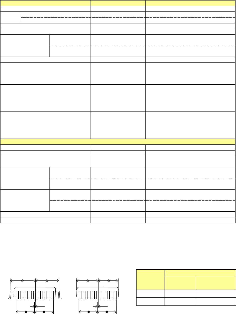
Note 2: The allowable distance “d” between the center of the lead rising section or of the body (Sc shown
in the figure) and the center of leads (Lc shown in the figure) of a component such as a QFP, SOP
and SOT is shown in the table below. If a component does not satisfy this allowable distance
requirement, the machine cannot attain the component placement accuracy described above.
Center of the body and that of the leads
Sc
Lc
d
Sc
Lc
d
Lead pitch
Allowable value “d”
□ 24.5 or less More than □ 25.4 to
□ 33.5 or less
0.8 or more
73μm 52μm
0.65
15μm 15μm
Allowable value “d”
Part 1 Basic Operation Chapter 1 Overview of the Machine
1-25
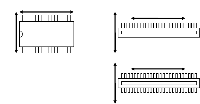
Note 3: Right angles to a lead and the direction parallel to a lead described for the accuracy of an SOP,
unidirectional lead connector, and bidirectional lead connector and a component whose image is
divided to be recognized are shown in the figure below.
Note 4: Since a BGA component position cannot be corrected with recognition of its image under the
following conditions, the component placement accuracy cannot be guaranteed.
①
Contrast between a solder ball and the surface of a board to which the solder ball is applied is
not clear enough. (Excluding a BGA whose body is ceramic)
②
A pattern whose thickness is the same as the diameter of a solder ball is connected to the ball,
and the ball cannot be recognized separately.
③
There is a through-hole or similar hole whose diameter is the same as that of a solder ball on
the board to which the ball is applied.
Right angles to a lead
Direction parallel to a lead
Right angles to a lead
Right angles to a lead
Direction parallel
to a lead
Direction parallel
to a lead