RS-1_instruction manual.pdf - 第974页
Part 2 D etaile d Descript ion of E ach Functi on Chapter 12 Handling th e Optional Device s 12 - 90 When you use a coplanar ity sensor, you have to oper ate the key for the coplanarity sensor . Insert the key into th e …
Part 2 Detailed Description of Each Function Chapter 12 Handling the Optional Devices
12-89
12.14 Coplanarity
12.14.1 Overview of the function
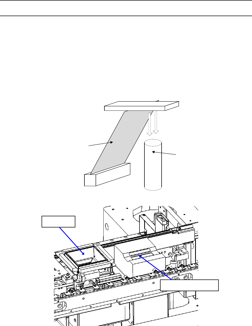
This is a coplanarity inspection unit that inspects electronic component with a laser line.
By moving a component, which is an object to be measured, in the direction (Y direction)
perpendicular to a laser line (X direction) at certain speed, the machine uses a camera to shoot
diffuse reflection of a laser beam emitted to the measured object to create its 3-D image, that is, the
machine measures displacement without touching it.
◇ This unit determines that a component can be accepted (checks the height of an electrode)
based on the component information sent from the machine in advance and the obtained 3-D
image.
レーザビーム
カメラ
Camera
Laser beam
VCS unit
Coplanarity sensor
Part 2 Detailed Description of Each Function Chapter 12 Handling the Optional Devices
12-90
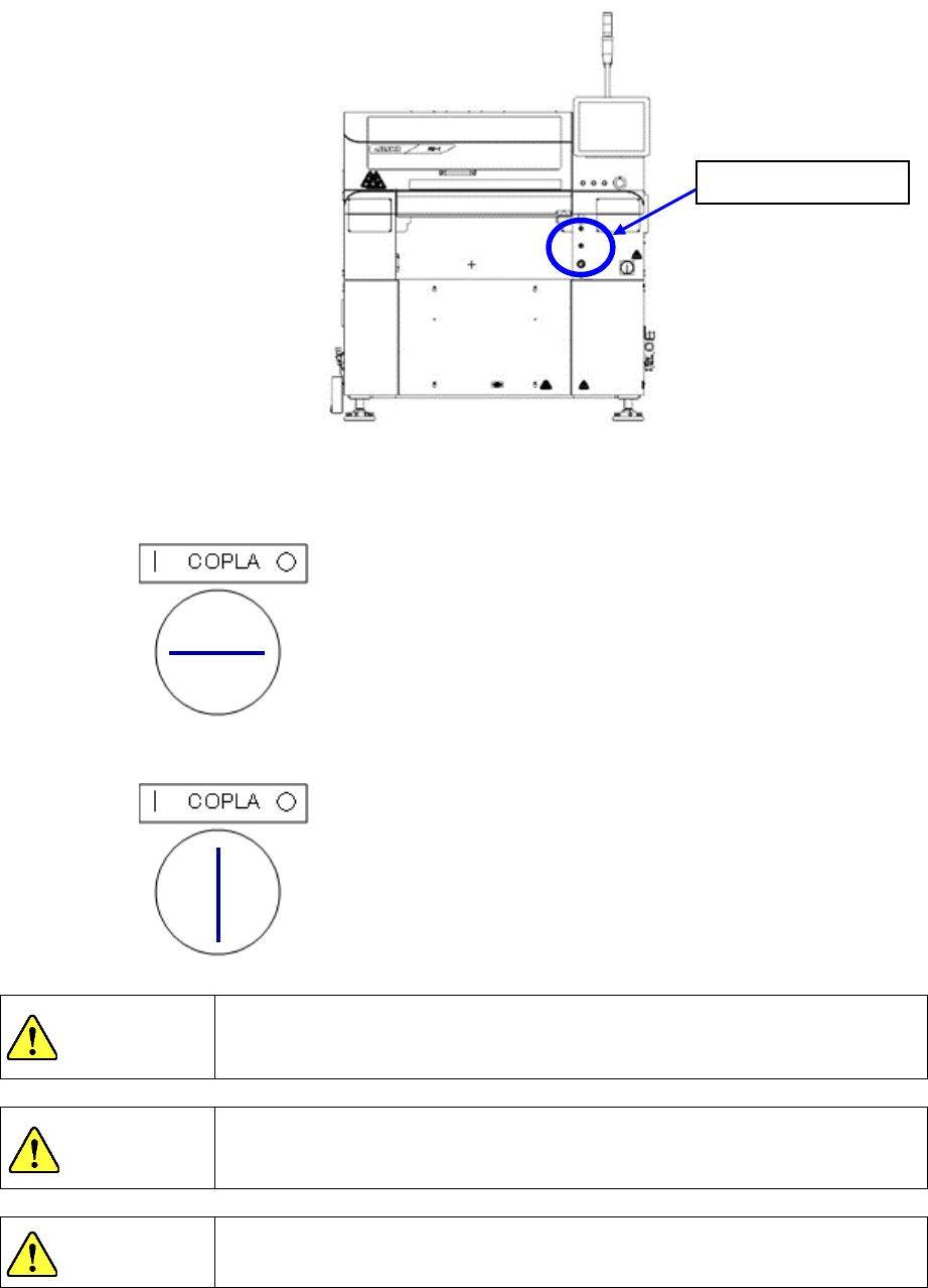
When you use a coplanarity sensor, you have to operate the key for the coplanarity sensor. Insert
the key into the machine, and turn it counterclockwise. The coplanarity sensor can be used.
◇ When the coplanarity sensor can be used
◇ When the coplanarity sensor cannot be used
The coplanarity sensor uses a Laser Class 3B product.
Exposure of an eye or skin to a laser beam is dangerous. Never look
directly at a laser beam nor touch it.
When the cover is opened, you cannot use the coplanarity sensor even
though the machine is in Maintenance mode. The sensor neither scans
nor radiates laser.
If you control or adjust the unit according to a procedure other than that
regulated in this document, it may expose you to dangerous laser radiation.
DANGER
CAUTION
CAUTION
Coplanarity key
Part 2 Detailed Description of Each Function Chapter 12 Handling the Optional Devices
12-91
12.14.2 Items to be inspected with a coplanarity check
12.14.2.1 Colinearity check
This check inspects whether a side on which a lead is located is “bent upwards or downwards.”
◇ This check is run with “one scanning operation.” For example, each of “four sides of a 4-side
element such as a QFP” or each of “two sides of a 2-side element such as an SOP” is
inspected with one scanning operation.
“Colinearity” means parallelism.
A colinearity check can be run for a lead component only.
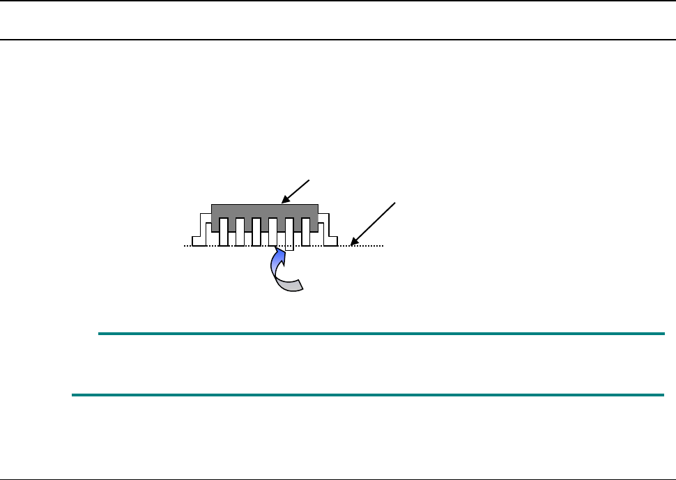
12.14.2.2 Coplanarity check
To calculate coplanarity, two methods are provided:
Coplanarity (uniformity of the bottom of a terminal) of a QFP/SOP can be calculated with the 3-point
method (JEDEC standard: JESD22-B108A) or the least-square method (JEDEC standard:
JESD22-B108A).
■ The 3-point method is selected at the factory.
This setting can be changed on the “Machine Setup” screen (See Section 8.3.6.8
“Coplanarity”).
◇ Coplanarity of a QFP or an SOP can be calculated with the 3-point method or the least-square
method.
◇ Coplanarity of a ball component can be calculated with the least-square method.
Measurement line
This lead is bent downwards
Element to be checked