RS-1_instruction manual.pdf - 第897页
Part 2 D etaile d Descript ion of E ach Functi on Chapter 12 Handling th e Optional Device s 12 - 13 3) Insert the tr ay holder , separate the side pl ate and the lock holder in t he place where the si de plate is in con…
Part 2 Detailed Description of Each Function Chapter 12 Handling the Optional Devices
12-12
12.2.1 Replacement of tray holder
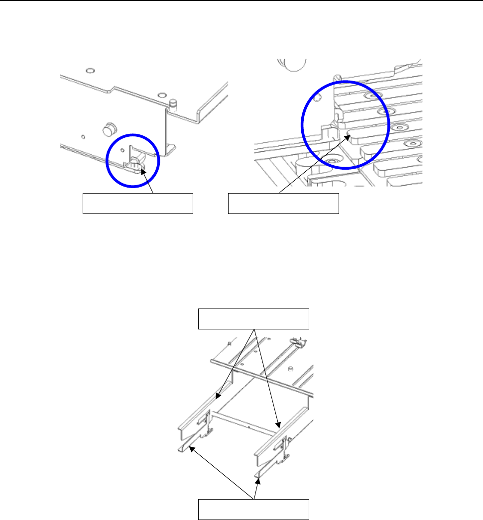
1) Insert the slide rail tip in the guide rail groove of a rear bank.
2) When inserting the tray holder up to the middle, grasp the side plate and the lock holder, and
open the lock holder.
Slide rail tip
Guide rail
Side plate
Lock holder
Part 2 Detailed Description of Each Function Chapter 12 Handling the Optional Devices
12-13
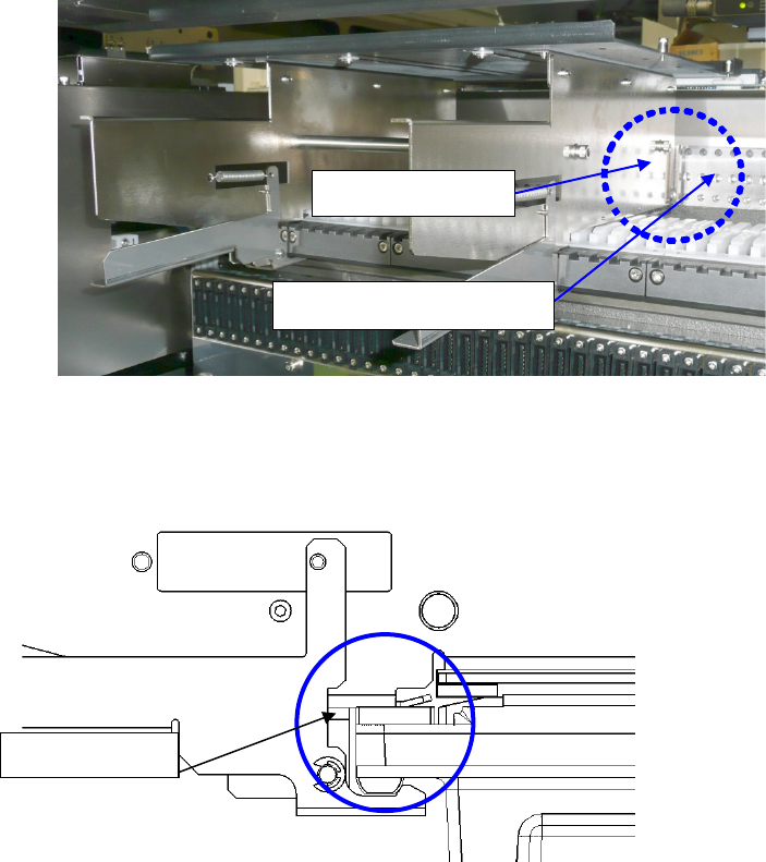
3) Insert the tray holder, separate the side plate and the lock holder in the place where the side
plate is in contact with the POSITIONING_PLATE, and lock it with the lock holder.
Note) Check to see if the tray holder is locked with the lock holder.
4) Detach it with the reverse procedures of the above.
Lock holder
Side plate
POSITIONING_PLATE

Part 2 Detailed Description of Each Function Chapter 12 Handling the Optional Devices
12-14
12.3 Installing the Matrix Tray Server (MTS)
This is a device to allow direct pickup by the main unit head and multiple-feed. (Rear bank
installation)
SR-1 can be used TR8SR, TR5SNX and TR5DNX.
Refer to the MTS Instruction Manual for details on handling and setting.
To avoid any accident caused by sudden activation of the machine, turn
off the power.
12.3.1 Setting up RS-1/1R (When a TR8SR is selected)
1) Removal of reel holder B. In the case of the fixed bank specification, it is placed on the floor
and removed as it is.)
CAUTION