RS-1_instruction manual.pdf - 第52页
Part 1 B asic O peration Chapter 1 Overv iew of the Machine 1- 34 ◇ The followi ng figure show s the interface circuit s for READY OUT s (IN) and BO ARD A V AILABL E signals . They confor m to t he SMEM A standard. GND (…
Part 1 Basic Operation Chapter 1 Overview of the Machine
1-33
①
②
①
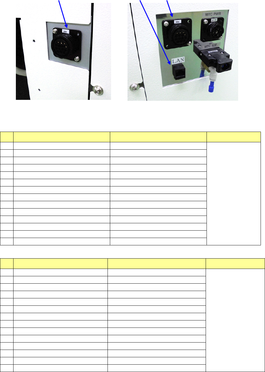
Left side of the front of the main unit (XL)
Right side of the front of the main unit (XL)
List of connectors on the left side panel
No.
Signal name (left to right) Signal name (right to left) Connector used
1
READY OUT
+
READY IN
+
AMP
206043-1
Connection of
the cable end
206044-1
2
READY OUT
-
READY IN
-
(GND)
3
BOARD AVAILABLE IN
+
BOARD AVAILABLE OUT
+
4
BOARD AVAILABLE IN
-
(GND)
BOARD AVAILABLE OUT
-
5
N.C.
N.C.
6
N.C.
N.C.
7
N.C.
N.C.
8
N.C.
N.C.
9
N.C.
N.C.
10
N.C.
N.C.
11
N.C.
N.C.
12
N.C.
N.C.
13
N.C.
N.C.
14
N.C.
N.C.
List of connectors on the right side panel
No.
Signal name (left to right) Signal name (right to left) Connector used
1
READY IN
+
READY OUT
+
AMP
206043-1
Connection of
the cable end
206044-1
2
READY IN
-
(GND)
READY OUT
-
3
BOARD AVAILABLE OUT
+
BOARD AVAILABLE IN
+
4
BOARD AVAILABLE OUT
-
BOARD AVAILABLE IN
-
(GND)
5
N.C.
N.C.
6
N.C.
N.C.
7
N.C.
N.C.
8
N.C.
N.C.
9
N.C.
N.C.
10
N.C.
N.C.
11
N.C.
N.C.
12
N.C.
N.C.
13
N.C.
N.C.
14
N.C.
N.C.
Part 1 Basic Operation Chapter 1 Overview of the Machine
1-34
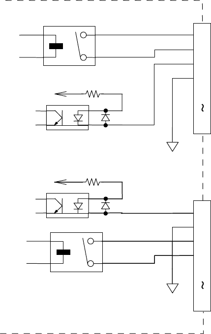
◇ The following figure shows the interface circuits for READY OUTs (IN) and BOARD AVAILABLE
signals.
They conform to the SMEMA standard.
GND(24V)
+
+
24V_
3.3K 1/4W
READY OUT +
BOARD AVAILABLE IN +
READY OUT -
BOARD AVAILABLE IN -
N.C.
1
2
3
4
5
14
READY IN +
BOARD AVAILABLE OUT +
READY IN -
BOARD AVAILABLE OUT -
N.C.
1
2
3
4
5
14
+
24V_
3.3K 1/4W
+
GND(24V)

Part 1 Basic Operation Chapter 1 Overview of the Machine
1-35
Applicable components and packaging styles
(1) Applicable component sizes
<RS-1/1R >
Unit: mm
Recognition method
Applicable size Remarks
Length x
width
Component
dimensions
Laser
recognition
LNC120-8 (Note 4) 03015 to □50
Note: If a 03015 component cannot
be recognized stably due to its shape
(for example, if a string art image is not
displayed normally), use a VCS (10-mm
field of view camera) (optional).
Batch vision
recognition
(See Note 1.)
54 mm view
camera
(See Note 2.)
Reflected illumination
□3.0 to □50.0
Mold size □1.7mm or more
Transmitted illumination □3.0 to □50.0
27 mm view
camera
Reflected illumination
1005~□24.0
Transmitted illumination
□3.0~□24
10 mm view
camera
Reflected illumination
0.25x0.125~□8
Transmitted illumination
□3~□8
Vision division
recognition
(See Note 1)
54 mm view
camera
Reflected illumination
Maximum: 50 x 150 (when
divided into 1 x 3)
□74 (when divided into 2 x
2)
Mold size □1.7mm or more
Transmitted illumination
Maximum: 50x120 (when
divided into 1 x 3)
Mold size □1.7mm or more
Short side 17mm or more
27 mm view
camera
Reflected illumination
~
24x72
(
1x3
)
~□48(2x2)
10 mm view
camera
Reflected illumination ~□16(2x2)
Component
height
Laser recognition LNC120-8
Category 1 0.05 to 1
See "(2) Recognition height of laser recognition
component".
Category 3
0.05 to 3
Category 6
0.05 to 6
Category 12
0.05 to 12
Category 20
0.05 to 20
Category 25
0.05 to 25
Batch vision
recognition
54 mm view camera
0.01 to 25
For the height restriction according to the
component size, see "(3) Recognition height of
image recognition component".
27 mm view camera
0.01
~
25
10 mm view camera
0.01
~
25
Vision division
recognition
54 mm view
camera
Diagonal line length,
less than 86
0.01 to 25
Diagonal line length, 86
or more
0.01 to 2.0 or 10.0
27 mm view camera
0.01
~
25
10 mm view camera
0.01~25
Lead pitch
Laser
recognition
LNC120-8 0.65 or more
Lead pitches and ball pitches cannot be
recognized by laser recognition.
VCS
recognition
(See Note 3)
54 mm view camera
0.38 to 2.54
27 mm view camera
0.20
~
2.54
10 mm view camera
0.2~0.5
Ball pitch
Laser
recognition
LNC120-8 1.00 to 3.00
Lead pitches and ball pitches cannot be
recognized by laser recognition.
VCS recognition
(See Note 3)
54 mm view camera
0.50 to 3.00
27 mm view camera
0.25~2
10 mm view camera
0.1~0.5
Ball diameter
VCS recognition
(See Note 3)
54 mm view camera
φ
0.3 to
φ
1.0
27 mm view camera
φ0.10~φ0.63
10 mm view camera
φ0.04~0.2
Lead length
VCS recognition
(See Note 3)
54 mm view camera 0.4 -
Lead pitches and ball pitches cannot be
recognized by laser recognition.