RS-1_instruction manual.pdf - 第421页
Part 1 B asic O peration Chapter 4 Cr eating a Produc tion Progra m 4- 86 (9) Vision dat a Enter the inform ation to perform c entering for the center of the component by VCS camer a. The informat ion to be set depends o…

Part 1 Basic Operation Chapter 4 Creating a Production Program
4-85
Setting items for each component type
Electrode
Measurement
Height Offset
Lead Offset
Width
Length
Bottom
Right
Top
Left
QFP
○
○
○
○
○
○
○
PQFP (BQFP)
○
○
○
○
○
○
○
SOP
○
○
○
○
×
○
×
TSOP2
○
○
○
○
×
○
×
CON2
(Bidirectional lead connector)
○ ○ ○ ○ × ○ ×
CONZ
(Z-lead connector)
○ ○ ○ ○ × ○ ×
TSOP
○
○
○
×
○
×
○
CONN
(Unidirectional lead
connector)
Leads On
Top
○ ○ ○ × × ○ ×
Leads On
Bottom
○ ○ ○ ○ × × ×
BGA
×
×
○
×
×
×
×
FBGA
×
×
○
×
×
×
×
Others
×
×
×
×
×
×
×
Part 1 Basic Operation Chapter 4 Creating a Production Program
4-86
(9) Vision data
Enter the information to perform centering for the center of the component by VCS camera.
The information to be set depends on the component type
Vision centering is performed by recognizing a bright portion (lead, call, etc.) of the component
through the VCS camera.
At vision centering, it is impossible to detect a fault such as lead vend and ball deformation. In the
vision items, set the lead, ball size, defect detecting level, etc. required for centering and defect
detection.
• Components for vision centering
Component type Vision recognition Lead shape, etc.
Reference: Laser recognition
enable/disable
Square chip
O
O
Square chip p (LED)
X
O
Melf
X
O
Elec. Cap. (Aluminum electrolytic
capacitor)
O
Lead component
O
GaAsFET
O
Lead component
O
SOT
X
O
SOP
O
Lead component
O
HSOP
O
Lead component
O
SOJ
O
Lead component
O
QFP
O
Lead component
O
QFN
O
Lead component
O
PLCC (QFJ)
O
Lead component
O
PQFP (BQFP)
O
Lead component
O
TSOP
O
Lead component
O
TSOP2
O
Lead component
O
BGA
O
Ball component
O
FBGA
O
Ball component
X
Outline-recognized component
O
Components whose
outline is to be recognized
X
General-purpose vision component
O
Components whose
outline is to be recognized
X
RNA (Network resistor)
X
O
Trimmer
X
O
One-direction lead connector
O
Lead component
O
Two-direction lead connector
O
Lead component
O
Z-lead connector
O
Lead component
O
Expanded-lead connector
O
Lead component
X
J-lead socket
O
Lead component
O
Gull-wing socket
O
Lead component
O
Socket with bumper
O
Lead component
O
Other
X
O
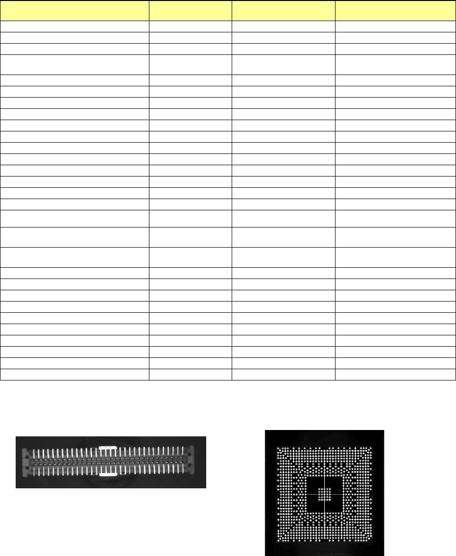
Example 1) For connector component
(lead recognition)
Example 2) For BGA component
(ball recognition)
Part 1 Basic Operation Chapter 4 Creating a Production Program
4-87
Left
Right
Bottom
Left
Top
Bottom
Top
Bottom
Top
Right
Left
Right
Right
Left
Top
Bottom
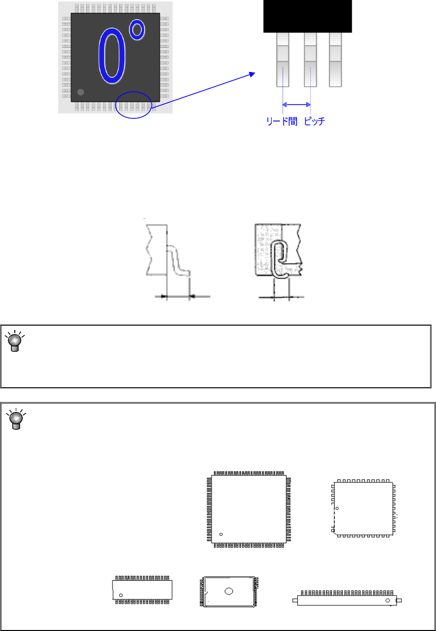
1) Component type: Lead component
① Lead pitch
Enter the distance between two consecutive leads.
② Lead Info.
a) Length
Enter the length of leads. Enter the length of a lead here. Although four fields for the
length are provided: “Bottom,” “Right,” “Top” and “Left,” which field(s) has (have) to be
entered varies depending on the component type.
Since the lengths of four sides of a QFP component are the same as each other, you have
to enter the length in the “Bottom” field only.
Lead length Lead length
Enter into these fields a value used for recognizing a component with a VCS.
For a QFJ, leads are located even insides of the molded section (bottom of the
component), so you may enter a value a little bit greater than the length of a lead
viewed from the top of the component.
Enter a value in each field of the “Bottom,” “Right,” “Top” and “Left” on the “Vision” data
screen with regarding the component placement angle “0 degrees” defined with the
machine as the reference.
Pitch between leads