RS-1_instruction manual.pdf - 第879页
Pa r t 2 Det ai l ed Des c r i pti on o f Ea c h Fu nc ti on Chapte r 1 1 S el f - diagnosis Func ti on 11 - 21 VCS cam era o ff set W hen you sel ect the [VC S off set] com m and fr om t he “ Sel f Chec k ” m enu, the “…
Part 2 Detailed Description of Each Function Chapter 11 Self-diagnosis Function
11-20
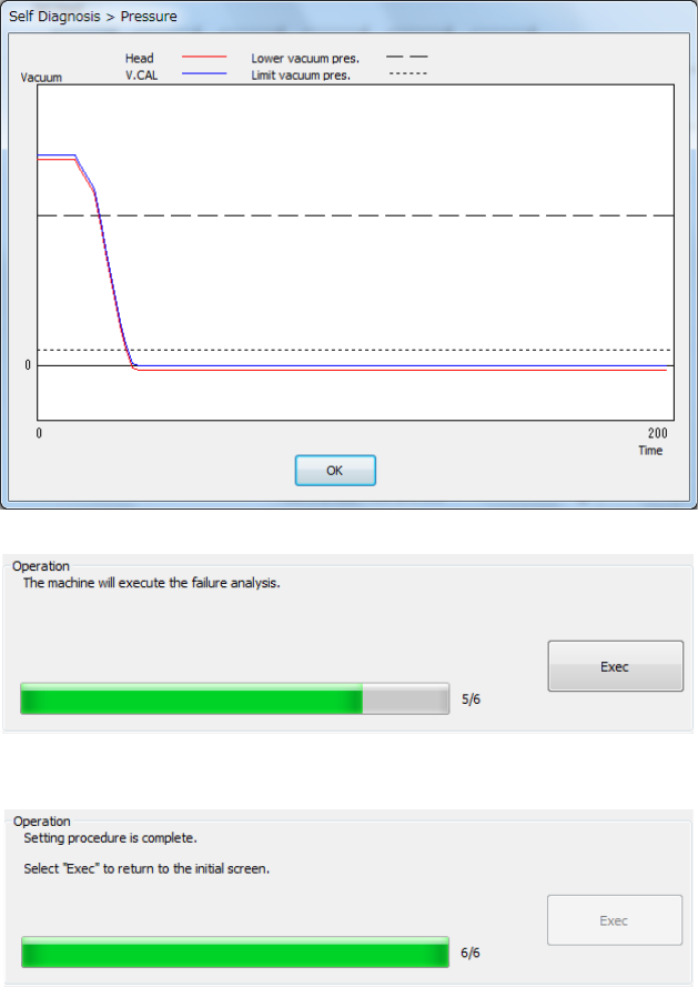
The set head is moved onto the vacuum calibration and the pressurized break status is
measured 3 times.
- The mean values between the 2nd and 3rd measurements are displayed.
- The graph of the pressure value displayed after measurement shows the data of the 3rd
measurement.
- Press <Exec>.
Part 2 Detailed Description of Each Function Chapter 11 Self-diagnosis Function
11-21
VCS camera offset
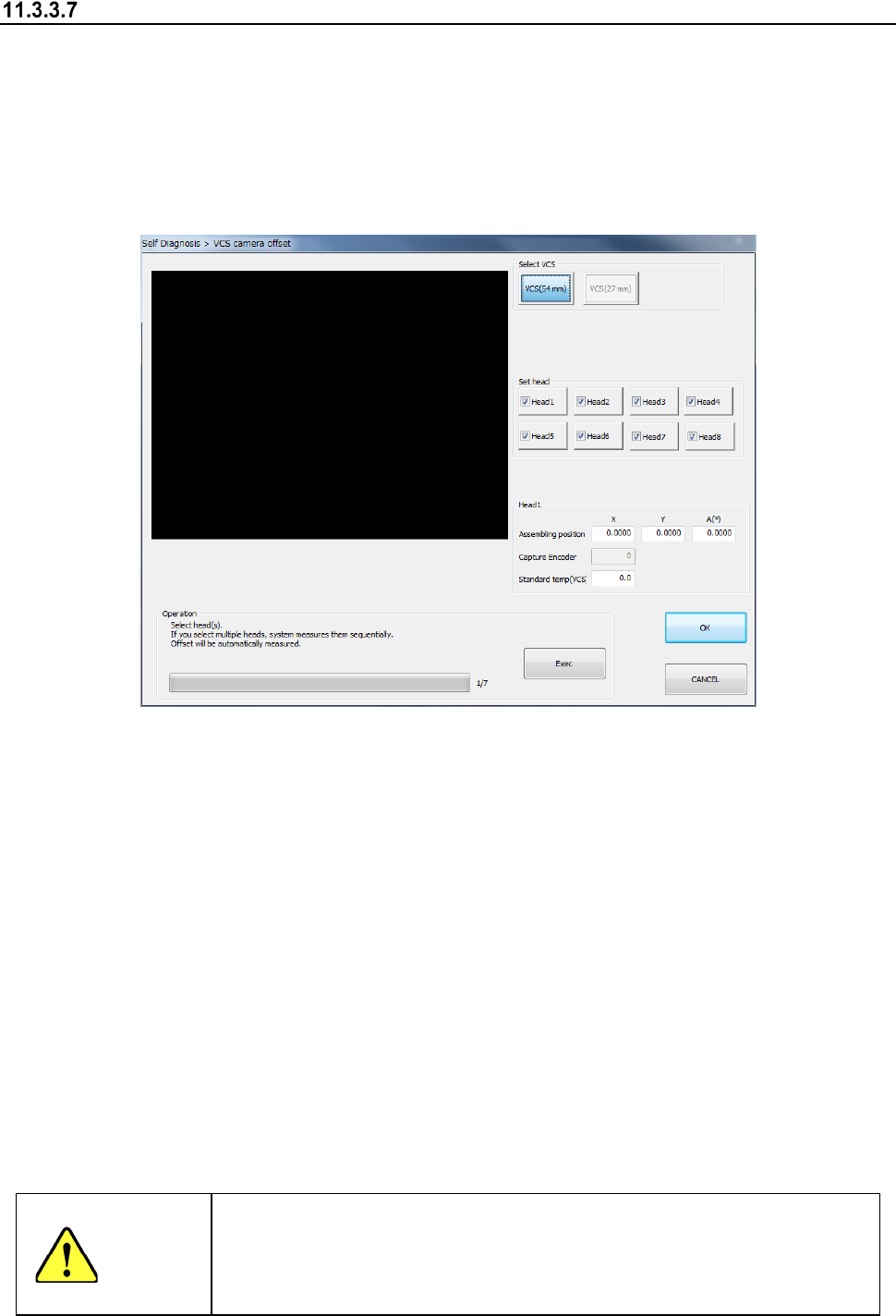
When you select the [VCS offset] command from the “Self Check” menu, the “VCS camera offset”
dialog box appears on the screen.
This screen allows you to set an offset value viewed from the designed position of each VCS
camera.
Reset an offset value only if a component recognized with a VCS is placed at a position shifted
from the regulated position in a certain direction.
A bare chip is used to set a VCS camera offset.
(1) Select VCS
Select a VCS to be set with the corresponding radio button displayed in the “Select VCS”
column.
(2) Head nozzle selection
Select a head to be measured with the corresponding check box.
You can select two or more heads to be measured at the same time.
(3) Assembling position/angle (Head 1)
The values saved with the MS Parameter and the set results are displayed here.
(4) Operation
1) Progress bar
The progress of measurement is displayed with this bar. When measurement finishes, it
indicates “100 %.”
2) <Exec> button
When you press the <Exec> button, each head unit moves to the waiting position to start
measurement.
See the following subsection “How to set” for details.
WARNING
When you press the <Exec> button, the axes start moving.
Before pressing the <Exec> button, be sure to check to see if there is no
one who is operating inside the machine. To prevent injuries, do not put a
hand inside the machine or close your face or head to the machine while
the machine is operating.

Part 2 Detailed Description of Each Function Chapter 11 Self-diagnosis Function
11-22
11.3.3.7.1 How to set
Perform the operation as instructed in the “Operation” column while holding down the <Exec>
button. The machine automatically obtains the values.
Operations to be performed until you finish making the required settings are described below.
(1) Nozzle allocation
Attach the No. 7506 nozzle onto the head you set.
(2) Preparation of a jig
Place a jig on the center frame of the bare station.
(3) Absorption of a jig
The machine absorbs a jig from the bare station. If an error occurs, set the jig again.
(4) Movement of the set head
Move the set head to the recognition position of the VCS camera you have set.
(5) Recognition of the jig with a VCS
The machine recognizes the jig position with the VCS to measure the center position of the jig.
(6) Returning of a jig
The machine returns the jig to the station.
When the machine finishes measurement, the progress bar indicates “100 %.”
To repeat measurement, select the <Exec> button. When you select the <Exec> button, the
previous screen reappears.
To measure another VCS, select it with the “Select VCS” button. When you change the selected
VCS to another one, the initial screen appears.
When you press the <OK> button, the measured values become valid, but are not saved or set yet
at this point.
These values are actually set when you quit the application. See Section 11.3.3.4.2 “Saving the
settings and quitting the screen” for details.
When you press the <CANCEL> button, the measured values become invalid.