RS-1_instruction manual.pdf - 第989页
Part 2 D etaile d Descript ion of E ach Functi on Chapter 12 Handling th e Optional Device s 12 - 105 Name Descripti on Remarks wHead Head used to check t he copla narity 3: head 1 4: head 2 5: head 3 6: head 4 7: head 5…
Part 2 Detailed Description of Each Function Chapter 12 Handling the Optional Devices
12-104
① Restart mode
To restart the suspended operation when the machine pauses due to a coplanarity error or a
colinearity error, select one of the following buttons: <Cross-Check>, <Do Place> and <Do
not Place>.
Restart mode
Operation the machine performs when it restart the suspended production
Cross-Check
Rechecks a component that caused an error when a check was run.
Do Place
Ignores an error and places on a board a component that caused an error when
a check was run.
Do not Place
Discards a component that caused an error when a check was run without
placing it on a board.
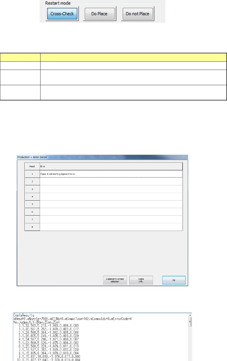
② Error Detail
When you press the <Error Detail> button on the “Stop” dialog box displayed due to a
coplanarity error or a colinearity error, the “Error Detail” dialog box appears on the screen.
When you select a head at which a coplanarity error or a colinearity error occurs, and then
press the <Copla Info.> button, information on the electrode set with the <Information of
Coplanarity> button on the “Inspection” tab invoked from the “Operation option” screen is
displayed on the Note Pad.
As the detailed information, the check results of each electrode, the X-coordinate and
Y-coordinate of the coplanarity sensor coordinate system, the Z-coordinate viewed from the
focus height, the coplanarity calculation result and the colinearity calculation result are output.
Part 2 Detailed Description of Each Function Chapter 12 Handling the Optional Devices
12-105
Name
Description
Remarks
wHead Head used to check the coplanarity
3: head 1
4: head 2
5: head 3
6: head 4
7: head 5
8: head 6
9: head 7
10: head 8
wNozzlw
Nozzle number
wATCNo
ATC number
wCompoType
Component type
wCompoIdx
Index of Component data
wErrorCode
Error code
No Electrode number
When the <All electrode information> button is selected on the
“Display” tab invoked from the “Production” tab of the
“Operation option” screen, electrodes are anticlockwise counted
from the No. 1 pin on the Top View as the No. 0 electrode.
When the <Only error
electrode information> button is selected,
the number indicates the order in which the machine detected
terminals.
Judge Check result
0: Terminal whose check result is “OK”
1: Terminal whose check result is “NG”
X
X-coordinate value of the coplanarity
sensor coordinate system
Y
Y-coordinate value of the coplanarity
sensor coordinate system
ZRaw
Z-coordinate value viewed from the
focus height
ZCop
Coplanarity calculation result
ZCol
Colinearity calculation result
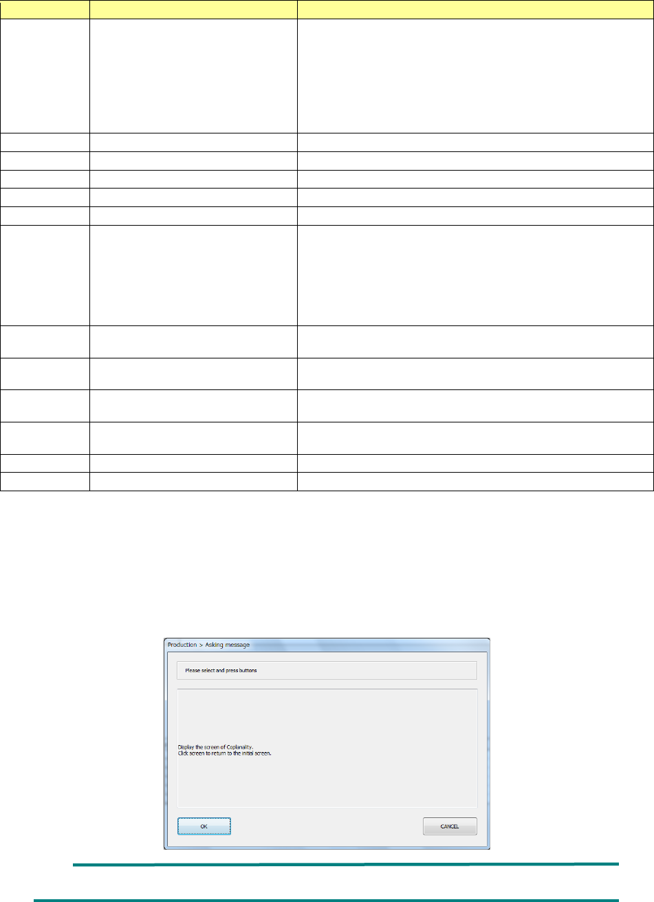
When you press the <Coplanarity > button in the “Screen selection” column of the “Stop” dialog
box displayed due to a coplanarity error or a colinearity error or when you press the <Coplanarity
screen selection> button on the “Error Detail” screen, the “Asking message” dialog box that asks
you whether to switch the current screen to the coplanarity scree appears on the screen. When
you press the <OK> button on this dialog box, the current screen is switched to the coplanarity
screen. When you press the <CANCEL> button, the machine redisplays the “Stop” screen.
When you touch the screen, the machine switches the coplanarity screen back to the production
screen.
It takes several seconds to finish switching the monitor screens.
Part 2 Detailed Description of Each Function Chapter 12 Handling the Optional Devices
12-106
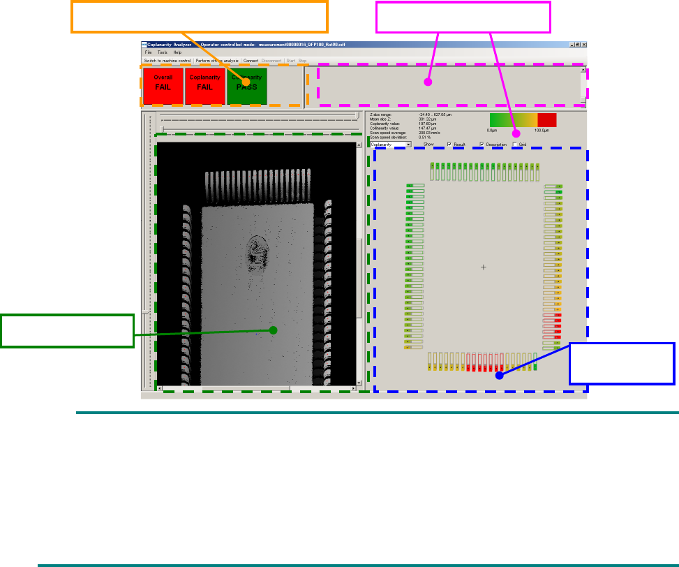
On the coplanarity screen, the “acceptance and rejection results,” “shot image,” “measurement
results” and “measurement logs” are displayed.
As the “acceptance and rejection result, the acceptance and rejection results of a coplanarity check
and those of a colinearity check, and the total results of the coplanarity check and the colinearity
check are displayed.
A 3-D image shot with the coplanarity sensor is displayed in the “shot image” area. If an electrode
is not displayed clearly enough, the measurement height is not adjusted correctly. Measure the
component height again. If the electrode is shot clearly, set a larger value for the exposure time on
the “Component” data screen.
The measured coplanarity value of an electrode is displayed in three-color gradation: green,
yellow and red in the “measurement results” area. A terminal displayed in red caused an error.
The “measurement result” of a colinearity check is displayed in preference to that of the coplanarity
check. If an error is found in both results of a colinearity check and that of a coplanarity check, only
the result of the colinearity check is displayed in the “measurement result” area.
If all terminals are displayed in green or yellow, but the “acceptance and rejection result” indicates
an error, a terminal(s) is (are) not detected correctly. Enter the correct lead width and the correct
terminal size.
The “measurement logs” area shows logs obtained during measurement. The information
displayed in this area is not used by the machine.
You cannot operate the coplanarity screen shown above.
Although the entire component is not displayed on the “shot image” area in some case, check
the shot state of the electrode displayed on the screen.
The language used on the coplanarity screen is determined according to the factory setting
regardless of the language displayed with the machine at the present. Although you switch
the displayed language to another one, the displayed language is not changed on the
coplanarity screen.
Acceptance and rejection result
Measurement logs
Measurement
result
Shot image