RS-1_instruction manual.pdf - 第217页
Part 1 B asic O peration Chapter 2 Pr oduction 2- 106 (1) C heck i ng to see if eac h VCS is st ained or n ot Item Description Reject Le vel Displays s ettings of the a verage va lue “Average R eject Level, ” the maxim u…
Part 1 Basic Operation Chapter 2 Production
2-105
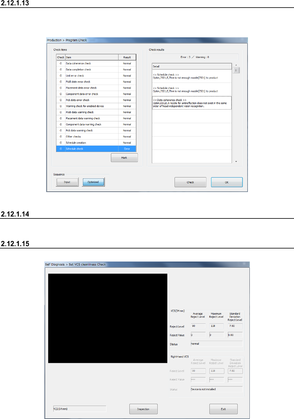
Program Check
This button allows you to check a production program before starting PWB production.
You can display the list of check items for a production program, and the system displays the check
results.
See Section 2.11.3 “Program Check” for details.
Laser check
See Section 2.12.5 “Laser height check” for details.
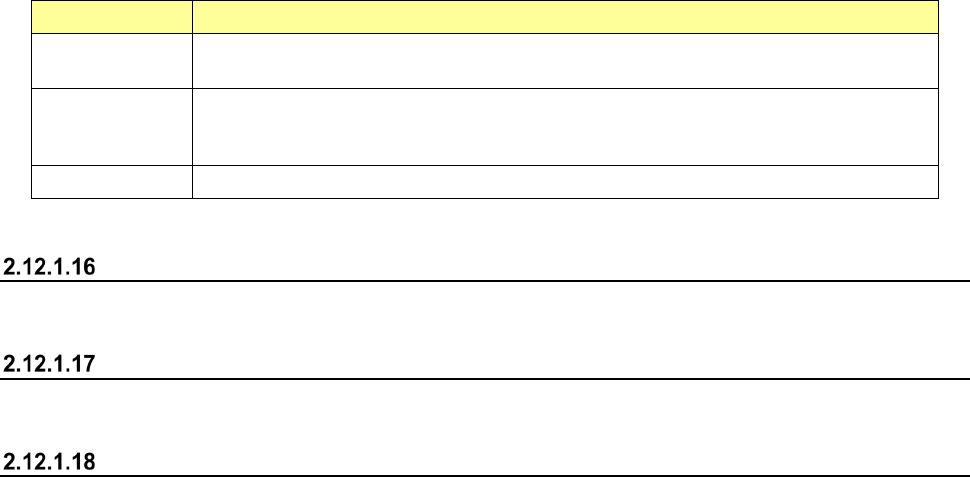
VCS Dirty Check
This button displays the results of the check of a standard VCS and a high-resolution VCS.
Part 1 Basic Operation Chapter 2 Production
2-106
(1) Checking to see if each VCS is stained or not
Item Description
Reject Level
Displays settings of the average value “Average Reject Level,” the maximum value
“Maximum Reject Level” and the standard deviation “Standard Deviation Reject Level.”
Reject Value
Displays the average value “Average Reject Level,” the maximum value “Maximum Reject
Level” and the standard deviation “Standard Deviation Reject Level” that are detected with
the check.
Status Displays the result if the corresponding VCS is stained.
See Section 11.3.3.3 “VCS Dirty Check” of Chapter 11 “Self-diagnosis Function” for details.
Verify All check
See Section 2.12.3 “Verify check (optional)” for details.
GNRL. Vision direction continuous inspection
See Section 2.12.4 “General vision component direction inspection” for details.
PWB Height
See Section "4-5-7-2 Measurement of mounting board surface height" in "Chapter 4 Program" for
details.
Part 1 Basic Operation Chapter 2 Production
2-107
Placement tracking
Overview
When you select the [Placement tracking] command from the “Support” menu invoked from the
“Product” menu, the “Placement tracking” screen appears.
On this screen, the system displays the list of placement operations before start of PWB production,
and displays each component placement position in order to allow you to check whether a
component is placed on a board already or not.
Therefore, you can decide whether to place a component on a board to produce PWBs
continuously.
“Placement tracking” screen
(1) List of placement operations
The system displays information on placements in sequence order on the upper left section of
the screen.
Menu item
Description
Head
Displays the number of a head that is to be used to place a component.
Circuit No.
Displays the number of a circuit on which a component is placed.
Step No.
Displays the number a step for placing a component.
Place ID
Displays the ID of a component to be placed.
X
Displays an X coordinate at which a component is to be placed.
Y
Displays a Y coordinate at which a component is to be placed.
Angle
Displays the angle of a component that is to be placed.
Comp. Name
Displays the name of a component that is to be placed.
(2) List of total placement information (“Production Information”)
The system displays the general component placement information.
Menu item
Description
Placement Sequence
Displays whether the placement sequence is in input order or optimized order.
Total circuit
Displays the total number of circuits that are to be placed on a board.
Total placements
Displays the total number of component placement positions on a board.
Total steps
Displays the number of components placed on a board with the selected station.
Not placed
Displays the number of component placement positions at which any component is
not placed yet with the selected station.