RS-1_instruction manual.pdf - 第84页
Part 1 B asic O peration Chapter 1 Overv iew of the Machine 1- 66 (7) Menu organizat ion of the Self Che ck screen No. Operation are a Sub menu 1 Stain check CAL Block Mark Filter stain VCS stain 2 Head Offs et Head Offs…
Part 1 Basic Operation Chapter 1 Overview of the Machine
1-65
(5) Menu organization of the Manual Control screen
No.
Operation area
Sub menu
1 Head
Head control
Head device control
Laser and sensor control
2
Conveyor
Conveyor control
3 Feeder
Electric feeder control
MTS control
MTC control
4 Other
Atc control
Signal light control
Other control
Other sensors
Drivers status
Servo status
Component verification l
Cutter control
VCS control
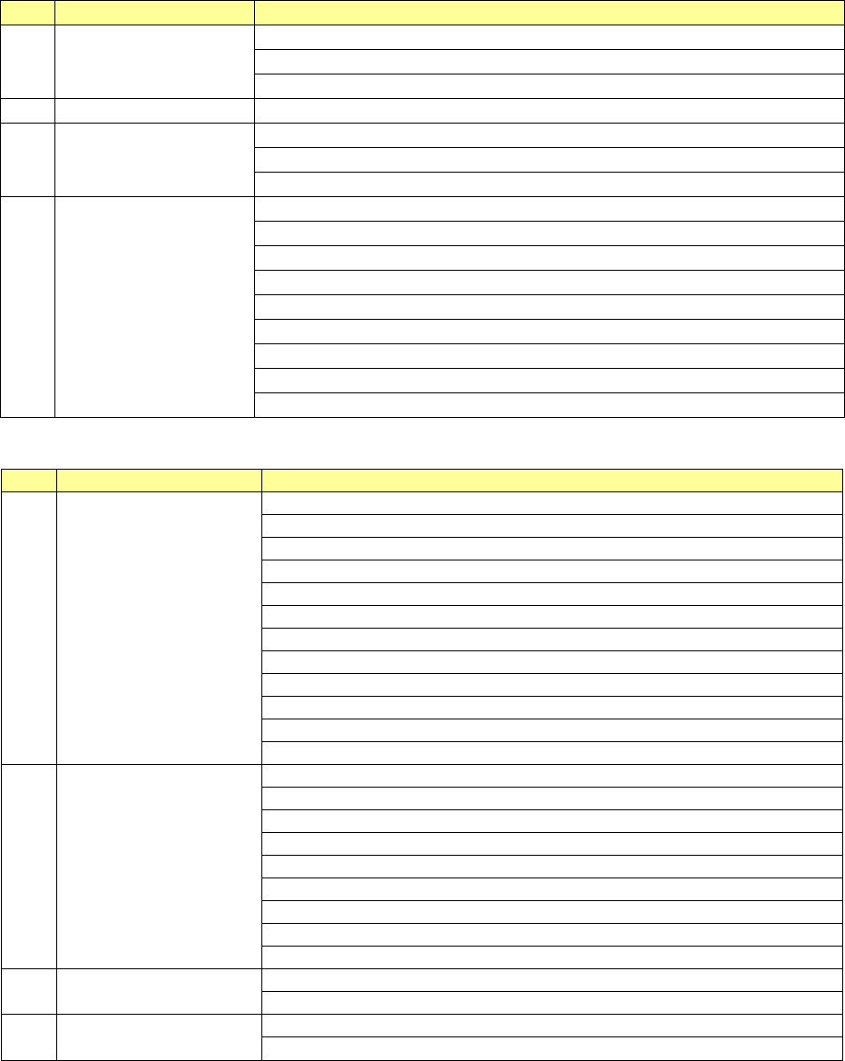
(6) Menu organization of the Machine Operation information screen
No.
Operation area
Sub menu
1 Machine
Machine Operation Information
Application Information
Asynchronous information
Operation Information of each nozzle
Operation Information of each head
Axis Information
Conveyor information
Vacuum Pump/Ejector operation information
ATC information
Signal Light information
Mini Signal Light information
Cutter information
2 Recognition/Inspection
OCC Information
Laser Information
HMS Information
VCS Information
SOT Information
Verify information
EPV Information
Copla usage Information
Transcription unit operation information
3 Setting
Setup – Operation Information of each nozzle
Setup – Operation Information of each head
4 Initialize
Reset
Clear all operation information
Part 1 Basic Operation Chapter 1 Overview of the Machine
1-66
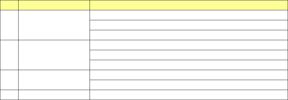
(7) Menu organization of the Self Check screen
No. Operation area Sub menu
1
Stain check
CAL Block Mark
Filter stain
VCS stain
2
Head Offset
Head Offset
Laser/sensor height
Vacuum
3 VCS offset
VCS offset
Multi-recognition offset
4 ATC Slide Plate ATC Slide Plate
Part 1 Basic Operation Chapter 1 Overview of the Machine
1-67
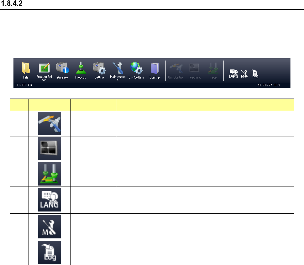
Configuration of the function buttons
The function buttons as well as the menus are displayed in the Operation area and the Information
area of the RS-1/1R screen.
(1) Function buttons in the Operation area
The function buttons are allocated in the Operation area as shown below.
No. Icon Name Overview
1
Unit control
If the quick control operation can be performed from the application
that is started up at the present, the machine starts the quick control
operation.
2
Teaching
If a teaching operation can be performed from the application that is
stated up at the present, the machine starts teaching.
3
Trace
If a tracking operation can be performed from the application that is
started up at the present, the machine starts trac
king control
operation.
4
LANG
(Language
selection)
This icon switches the displayed languages in real time.
5
M (Maintenance
information)
This icon displays the component replacement information screen.
If the machine has anything to notify an operator, a warning mark is
displayed above the icon.
6
LOG
(Getting a log)
This icon allows you to receive a log.
Some buttons may not be selected depending on the application that is being started up.