RS-1_instruction manual.pdf - 第742页
Part 2 D etaile d Descript ion of E ach Functi on Chapter 8 Machine Set up 8- 34 (2) H ow to set 1) Mark positi on correctio n Perfor m teaching for the first mark and second m ark of the MT S bank marks. Select a mark i…
Part 2 Detailed Description of Each Function Chapter 8 Machine Setup
8-33
MTS position offset
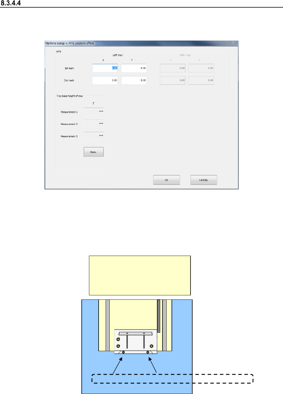
After you select [MTS position offset], the following screen appears.
Perform an MTS position offset setting.
Set mark position 1/2 of the tray.
(1) Setting item
1) Mark position correction
The mark position correcting function obtains an offset in the horizontal direction
(X, Y) to the design origin of the MTS band mark and corrects the pick coordinates of
the production program at component pick operation.
TR5S/TR5D/TR8SR
<Top surface drawing>
MTS
Front<--->Rear
First mark
Second mark
Mark position correction
Part 2 Detailed Description of Each Function Chapter 8 Machine Setup
8-34
(2) How to set
1) Mark position correction
Perform teaching for the first mark and second mark of the MTS bank marks.
Select a mark item for setting an offset value and press the device key ("HMS" or
"CAMERA") of the teaching panel. Then, the MTS bank marks are drawn out and
teaching is started. Check and adjust the position so that the teaching position may be
the center of the bank mark.
After completion of teaching, the X/Y offset value to the bank mark position on the
design is automatically input.
2 Tray base height display
Pressing the <Meas.> button will display the height at each measurement point.
Refer to the “Installation Guide” of each MTS for the detailed adjustment method.
Part 2 Detailed Description of Each Function Chapter 8 Machine Setup
8-35
MTC shuttle pick position
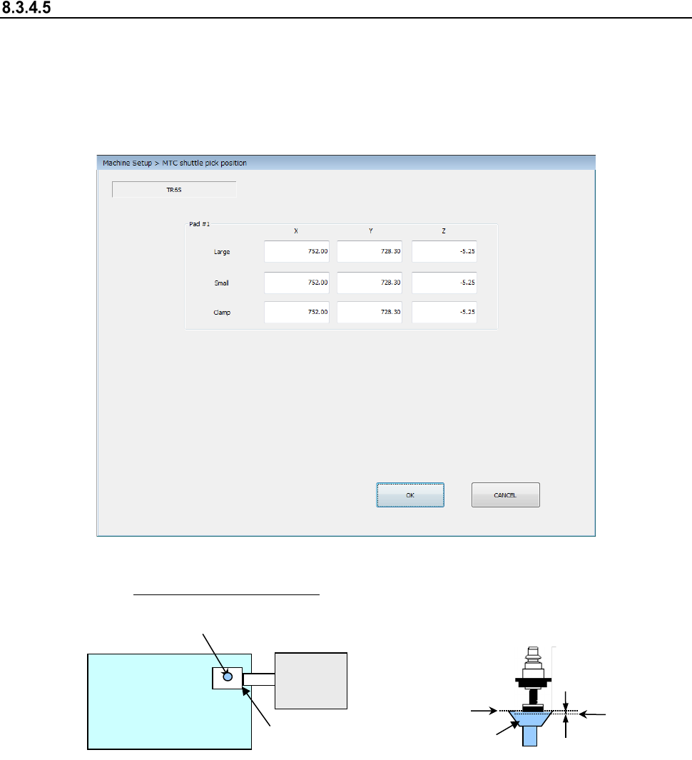
When you select the [MTC shuttle pick position] command, the following screen appears.
This screen allows you to specify the pick-up position (X, Y) of a component supplied from the
MTC.
Teach the position (X, Y) with the camera. Attach a 7508 nozzle on a head, and teach as the Z-
coordinate the height at which the bottom side of the nozzle comes in contact with the topside of
the pick-up pad of the shuttle on the MTC side.
(1) Setting item
① XY: Teach the center of the pad. ②
Z: Align the nozzle with the topside of the
pad, and then teach the position lower than
this side by 0.5 mm.
(2) How to set
Specify each coordinate with the teaching operation or using the keyboard.
When the input focus is in the “X” or “Y” field, the XY values are taught. When it is in the “Z”
field, the Z value is taught.
Teach the Z-coordinate while looking with eyes at the nozzle and the pad.
Note that the Z-coordinate of each of the “Large,” “Small” and “Clamp” fields is obtained and
displayed when one of them is taught.
MTC
<Top view>
Shuttle
Pad
0.5 mm
Z
Topside of
the pad