RS-1_instruction manual.pdf - 第257页
Part 1 B asic O peration Chapter 2 Pr oduction 2- 146 Tracki ng a component placement position You can displ ay the list of co m ponent pl acement positions and track wheth er a component is plac ed at each com ponent pl…
Part 1 Basic Operation Chapter 2 Production
2-145
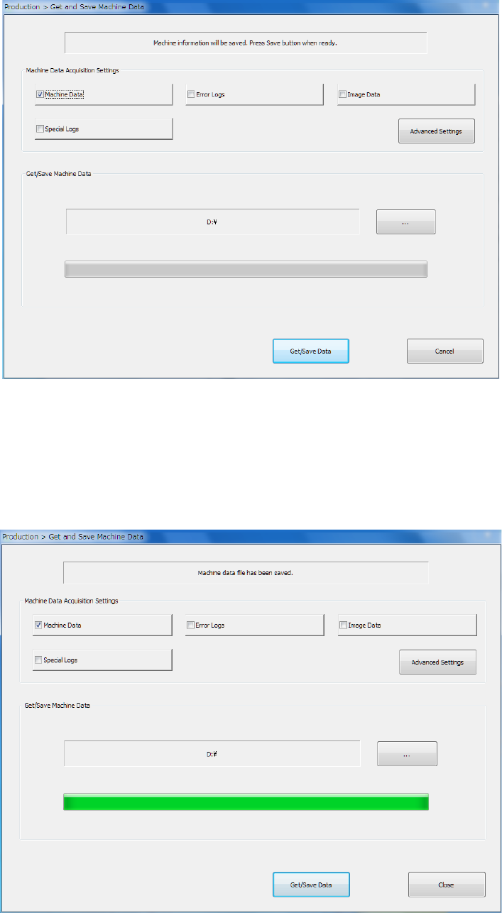
① Select the “Arrange” command from the menu, and then the [Get and Save Machine Data]
command from the “Arrange” menu.
② Press the <…> button to specify where to save the file.
③ When you click the <Get/Save Data> button, the system gets appropriate machine information
files, compresses the obtained files, and saves it.
④ When the machine information files have been obtained and compressed successfully, the
screen display is changed as follows.
To close this screen, press the <Close> button.
See Section 1.9.6 “Get and Save Machine Data” for details.
Part 1 Basic Operation Chapter 2 Production
2-146
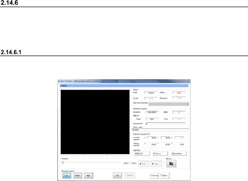
Tracking a component placement position
You can display the list of component placement positions and track whether a component is placed
at each component placement position to check it.
When you select the <Automatic> button or the <Manual> button as the “Place tracking” menu item
on the “Trial” production conditions screen or “Dry run” production conditions screen, the system
tracks a component placement position with a camera after placing a component on a board.
Automatic
When you select “Automatic” as the menu item “Place tracking,” the camera moves to the first
component placement position after a component is placed on a board. The system displays the
“Placement position tracking” screen for each station, and then the monitored image.
• After the camera stops at the position for the time specified in the “Tracking” field, and then
moves to the next component placement position automatically.
When the camera tracks a component whose dimension, width or length, is longer than 4.5
mm, it moves to four corners of the component.
• After PWB production, the camera tracks component placement positions continuously.
• To stop tracking component placement positions with a camera temporarily, press the
<STOP> switch of the operation panel.
• If you press the <STOP> switch when the camera pauses temporarily, the camera stops at
the current component placement position. If you press it when the camera is moving in
this case, the camera stops at the next component placement position.
• When you press the <Teaching> button of the function bar while the camera pauses during
tracking of a component placement position, the system can teach the placement position.
• You can enter a component placement position as a value directly.
When you enter a component placement position and press the <ENTER> button, the head
starts moving.
• When you press the <NEXT> button or the <PREV> button in the “Progress” column, you
can change a component placement position to be taught
- When you press the <START> switch, the system resumes automatic tracking of a
component placement position with a camera.
The head moves immediately to track a component placement position with a camera.
- When you press the <STOP> switch, the system displays the screen for asking you
whether to abort tracking operation, and then aborts tracking of a component placement
position with a camera.
Since the system replaces nozzles even though you press the <STOP> switch, the
XY-axes, nozzles and heads continue moving.
Part 1 Basic Operation Chapter 2 Production
2-147
CAUTION
- Check to see if there is no one who is operating the insides of the machine.
- Check to see if there is no one who is near the machine and may be injured.
- Check to see if there is no adjustment tool that may prevent each operation of the insides
of the machine is attached or placed to/in the machine.
- To prevent any accident causing injuries, never put your hand in the machine or never
bring your face or head close to the machine while it is operating.
Manual
When you select “Manual” as the menu item “Place tracking,” the camera moves to the first
component placement position after a component is placed on a board. Then, the system displays
the monitored image on the screen, and pauses temporarily.
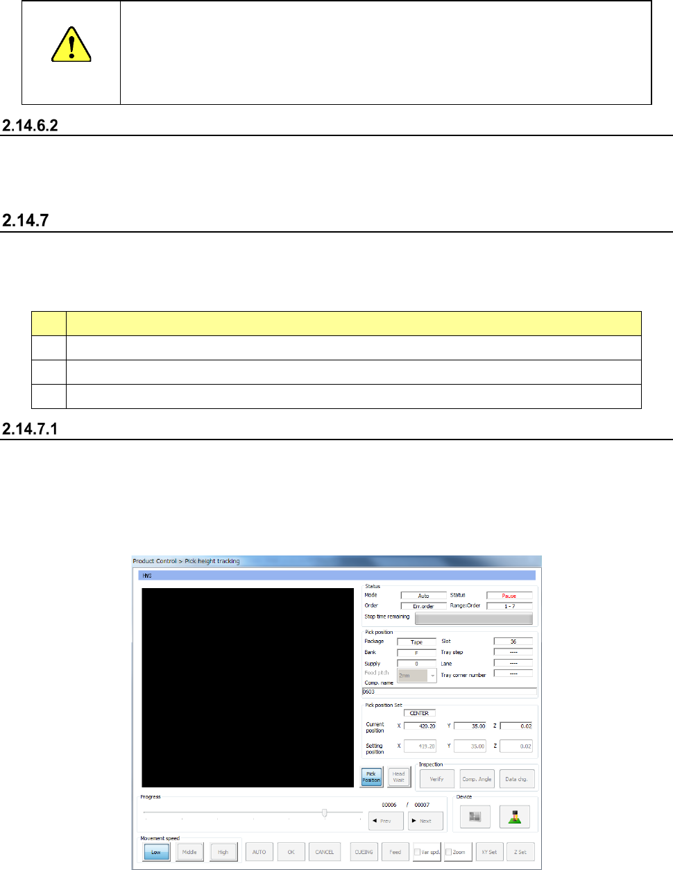
Tracking a component pick-up position with a camera
You can use a camera to track a component pick-up position before the system places a component
on a board. You can track a component pick-up position in the following cases described in the
table below.
See Section 4.5.6.5 Pick-up position/Pick-up height” of Chapter 4 “Creating a Production Program”
No.
Case
1
Tracking of a component pick-up position with a camera during Trial production or Dry run production
2
Tracking of a component pick-up position from the Retry list
3
Tracking of a component pick-up position from the “Error” screen or the “Stop” screen
Automatic
When you select “Automatic” as the menu item “Pick tracking,” the camera moves to the first
component pick-up position before a component is placed on a board.
The system displays the “Pick position tracking” screen and then the monitored image on this
screen.
After the camera stops at the position for the time specified in the “Tracking” field, it moves to the
next component pick-up position automatically.
• To stop automatic tracking component pick-up positions with a camera temporarily, press
the <STOP> switch of the operation panel.
If you press the <STOP> switch while the camera pauses temporarily, it stops at the current
component pick-up position. If you press the <STOP> switch while the camera is moving,
it stops at the next component pick-up position.
• When you press the <Teaching> button of the function bar while the camera pauses during
tracking of a component pick-up position, the system can teach the component pick-up