RS-1_instruction manual.pdf - 第134页
Part 1 B asic O peration Chapter 2 Pr oduction 2- 23 Configuration of the PWB transport unit <Name of eac h part of the conveyor (PWB transp ort unit)> 2 1 15 11 3 4 8 10 11 12 10 13 14 17 16 18 11 7 5 9 12 6 21 20…

Part 1 Basic Operation Chapter 2 Production
2-22
2.7 Preparation for PWB Production
Setting up a PWB
<Procedure>
How to set up each PWB production mode on the “Plan Support” screen *1 invoked from the
“Production” screen is described here.
The operations described below become available only after you start up the Production utility
unless otherwise noted.
*1 “Plan Support” screen invoked from the “Product” menu: When you select the [Support]
command from the menu invoked with the “Product” button of the main menu, and then the
[Plan Support] command, you can execute the function for selecting a check or adjustment to
be performed at preparation stage of PWB production by selecting the corresponding menu on
the “Production” screen. This improves the operability of the system.
See Section 4.5.2.5 “Transport” for the detailed description of transport of a PWB.
See Section 2.12.1 “Plan support” for the detailed descriptions of the plan support functions.
Note: You have to load a production program to the system in order to start up the Production
utility.
Positioning of the support pin
Adjustment of the PWB transport rail width
Part 1 Basic Operation Chapter 2 Production
2-23
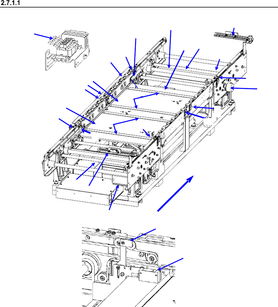
Configuration of the PWB transport unit
<Name of each part of the conveyor (PWB transport unit)>
2
1
15
11
3
4
8
10
11
12
10
13
14
17
16
18
11
7
5
9
12
6
21
20
22
23
Board transfer direction
1 IN sensor
9 Board transport electromagnetic
valve
17 Support pin detection sensor light receiving
section
2 OUTsensor
10 Conveyor motor
18 Stopper sensor
3 WAIT sensor fiber light receiving section
11 Drive shaft
19 Stopper
4 WAIT sensor fiber light emitting section
12 Side beam
20 (WAIT2 sensor fiber light receiving section)
5 C-OUT sensor fiber light receiving section
13 Support table IN
21 (WAIT2 sensor fiber light emitting section)
6 C-OUT sensor fiber light emitting section
14 Support table OUT
22 (WAIT2 sensor fiber light receiving section)
7 PWB guide
15 Automatic width adjustment motor
23 (WAIT2 sensor fiber light emitting section)
8 Support table origin sensor
16 Support pin detection sensor light
emitting section
18
19
Part 1 Basic Operation Chapter 2 Production
2-24
<Overview of the PWB transport unit construction>
Attach the conveyor stoppers on the right side when the PWB feeding direction is L to R; attach
them on the left side when the PWB feeding direction is R to L. When conveyor stoppers are used,
the PWB is clamped at the position where the front end of the PWB comes in contact with the
conveyor stopper on the downstream (i.e. OUT) side.
1) When a board is loaded to the machine, and the IN sensor ① detects it, the conveyor motor
⑩ drives the drive shaft ⑪ to cause the conveyor belt to start transporting it. Additionally, the
stopper 19 turns ON at the same time.
2) When the PWB reaches the stopper 19, the STOP sensor 18 detects it and the support tables
13 and 14 move up. At this time, the outer shape of the PWB is fixed by the stopper 19 and
support pin. After the PWB has been fixed temporarily, the stopper 19 turns OFF to finish fixing
the PWB.
3) After the PWB has been fixed, the next PWB is carried in in the same manner and it waits at the
position of the WAIT sensor 3.
4) When the system finishes producing a PWB, the fixed board (PWB) starts being ejected.
5) When the first PWB passes through the C-OUT sensor 5, the stopper 19 turns ON again to
make the preparations for fixing the next PWB.