RS-1_instruction manual.pdf - 第752页
Part 2 D etaile d Descript ion of E ach Functi on Chapter 8 Machine Set up 8- 44 ( 2) How to set 1) Sel ec t the se tting by chec k button. [Setting for use of a splice sensor] * Setting ite ms for ele ctric fee der (RF)…
Part 2 Detailed Description of Each Function Chapter 8 Machine Setup
8-43
Splicing setup
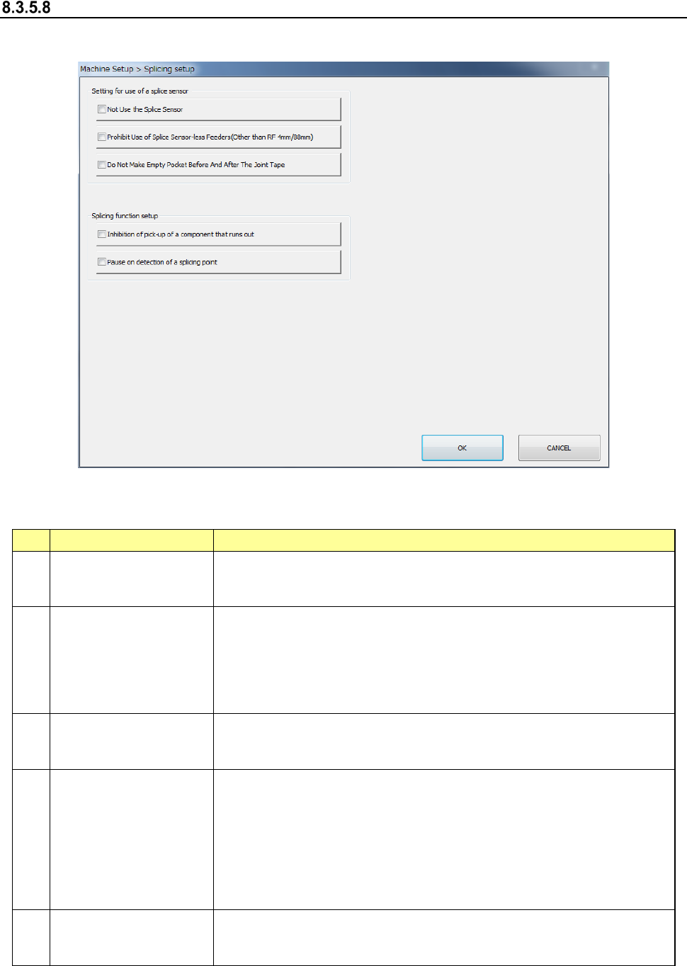
When you select [Splicing setup], the screen shown below will appear.
(1) Setting items
This tab allows you to make settings of connection to the IFS server.
No.
Setting item
Description
1
Not Use the Splice
Sensor
Does not use the splice sensor of the electric feeder (RF). Detects the
splicing point by detecting the number of pickup mistakes.
(Conventional method)
2
Prohibit Use of Splice
Sensor-less Feeders
(Other than
RF4mm/8mm)
Disables the electric feeder (RF) without splice sensor for the
production. An error occurs in the feeder without splice sensor during
check before production start. Additionally, the production stops when
the feeder without splice sensor is mounted during production.
Note: Since an RF04AS/RF88AS is not equipped with a splice sensor,
this setting item is not applied to them.
3
Do Not Make Empty
Pocket Before and After
the Joint Tape.
Stops the empty pocket before and after the joint tape after the retry
has been performed for the number of pickup retries. The splicing
point is detected only using the splice sensor detection.
4
Inhibition of pick-up of
a component that runs
out*
The parts not remained in [Production program] – [Number of parts
setting] from Production Menu shall be Out of Parts and suction
operation is not performed. In the case of “Not set”, production
continues even if the remaining number becomes 0.
When setting this item to be valid in case of external output, the setting
becomes valid by linking [Obtain remained number of parts from
external storage system] in [External output setting 2] of online
connection.
5
Pause on detection of
a splicing point*
When detecting a splicing point, production is paused in order to check
whether it is the splicing point or not. Production continues in case of
“Not set”.
* Refer to the instruction manual for Production Support System for function details.
Part 2 Detailed Description of Each Function Chapter 8 Machine Setup
8-44
(2) How to set
1) Select the setting by check button.
[Setting for use of a splice sensor] * Setting items for electric feeder (RF)
The setting items are used for the online production.
When the setting items are checked on, they cannot be used. When the setting
items are checked off, they can be used.
When [Setting for use of a splice sensor] is checked on, all subsequent items are
checked off and they cannot be selected.
[Splicing Function Setting]
At the setting for using when a check mark is put, it becomes “Not use” setting under
no check mark.
Setting is capable when the “Incorrect Mounting Prevention Function” of online
connection is valid.
Part 2 Detailed Description of Each Function Chapter 8 Machine Setup
8-45
8.3.6 Unit setting
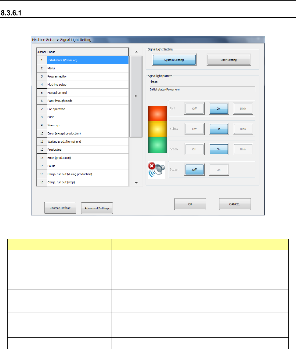
Signal light
When you select [Signal light], the following screen appears.
(1) Setting items
No. Item Description
1
Signal light setting
(System setting, User setting)
User Setting: This push button allows you to change the signal
light pattern.
System setting refers only to the initial values of the system set
pattern. You cannot change these settings.
2
Signal light pattern
(Red, Yellow, Green)
Sets the light pattern of the signal light for each operation phase.
Select OFF, ON and BLINK.
3
Signal light pattern (Buzzer)
Sets ON/OFF of the buzzer in each operation phase.
4
Restore Default
Copies the system setting data to the user setting data.
5
Advanced Settings Opens the Signal Light Advanced Settings screen.