RS-1_instruction manual.pdf - 第67页
Part 1 B asic O peration Chapter 1 Overv iew of the Machine 1- 49 (1) Flow of laser align c entering 1) For LNC120 - 8 ① ② ③ ④ ⑤ ⑥ Part attracting Pick the component by driving Z- axis, and adjust the component at laser …
Part 1 Basic Operation Chapter 1 Overview of the Machine
1-48
Centering system
Instead of using conventional mechanical centering system, this machine uses touchless centering
system where LED align sensor is used to read the position and angle of components. This can be
achieved by detecting the shade of the components created by the laser rays applied horizontally to
the components.
LNC120-8
By moving Z-axis up and down, a component is picked with vacuum, and the LED is applied to the
component. A shade is made where the LED is obstructed by the component. By turning the
component along q-axis, the shade changes.
◇ According to the change of the shade, offsets of the position and angle of the picked component
are calculated. These offsets are corrected when mounting.
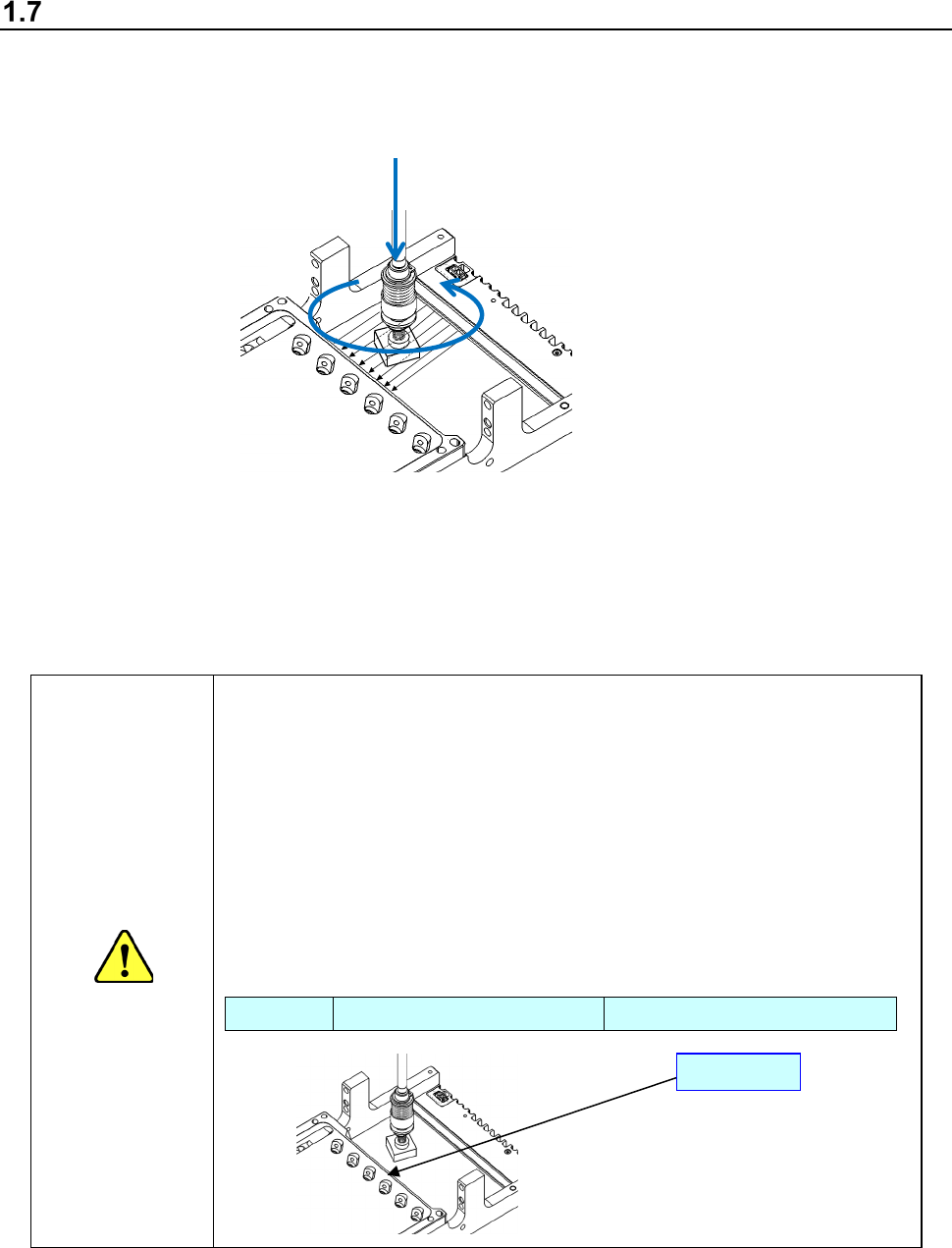
Caution
<Caution about protection of the laser unit glass>
If the surface of the glass that covers the component detecting section of the
laser unit is scratched, it causes a component recognition error with laser.
Note the following points to use the machine.
1. Do not use any component whose size exceeds the regulated maximum
component size.
2. Even though a component size is the regulated maximum component size
or smaller, the component may become in contact with the glass surface
when you change the component pick-up position.
Specifications (Maximum component size)
LNC120-8 Square component: □ 50 mm Length of a diagonal line: 70 mm
Glass
z
θ
Part 1 Basic Operation Chapter 1 Overview of the Machine
1-49
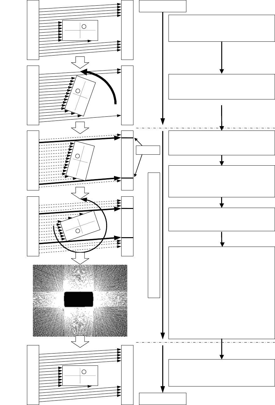
(1) Flow of laser align centering
1) For LNC120-8
①
②
③
④
⑤
⑥
Part attracting
Pick the component by driving
Z-axis, and adjust the
component at laser align height.
Rotation in θ direction starts.
While the θ-axis is accelerating, the system
does not start measuring a component.
Laser align measurement
Edge
When the speed of the rotation in θ direction
reaches the certain value, the system starts
laser align measurement.
Placement
The sensor obtains the edge position of the
area shadowed by a component.
The system saves a beam corresponding to
the edge position as a “tangent line” into the
sensor.
The system obtains the tangent line data on
each angle by rotating the θ axis 360
degrees.
When the θ axis finishes rotating by 360
degrees, the sensor generates and
analyzes the outer shape of a component
based on the tangent line data obtained at
each angle to return the measurement
result to the mounter.
- Component size
(X direction: wX Y direction: wY)
- Distance between the center of the
nozzle rotation and the center of a
component
(X direction: dX Y direction: dY)
- Angle (θ) error: dRz
The system corrects the following errors
and places a component on a board.
Positioning error (dX, dY)
Angle error (dRz)
Part 1 Basic Operation Chapter 1 Overview of the Machine
1-50
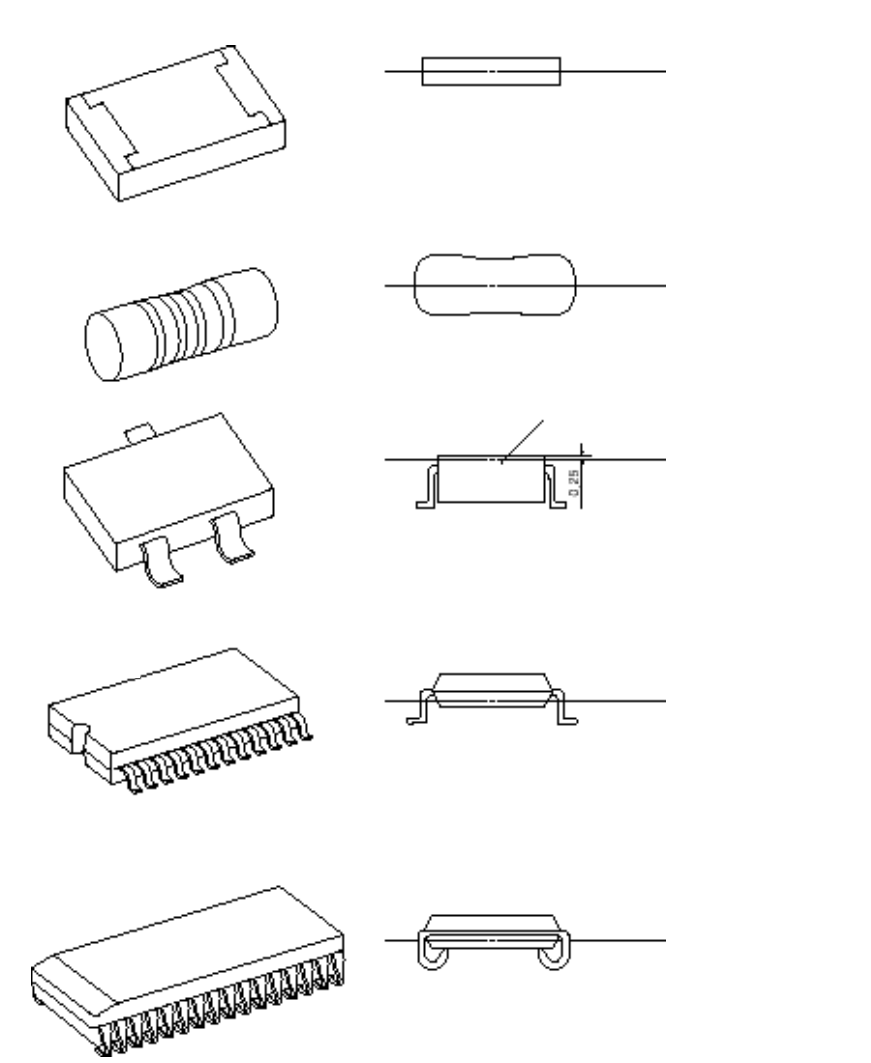
(2) Laser align measurement position for major component types
Mold
Square chip
MELF
SOT
SOP/TSOP
SOJ
(Center between the top and bottom
surfaces of the component)
(Center of the component)
(0.25 mm above the top of the component)
(Center between the bottom surface of the
component and the foot of the leads)
(Center between the bottom surface of the
component and the foot of the leads)
Laser align
measurement position
Laser align
measurement position
Laser align
measurement position
Laser align
measurement position
Laser align
measurement position