RS-1_instruction manual.pdf - 第932页
Part 2 D etaile d Descript ion of E ach Functi on Chapter 12 Handling th e Optional Device s 12 - 48 12.7.5 Sponge for Supporting a Long - sized Boar d Th is is a part for preven ting a long - sized b oard from flap ping…
Part 2 Detailed Description of Each Function Chapter 12 Handling the Optional Devices
12-47
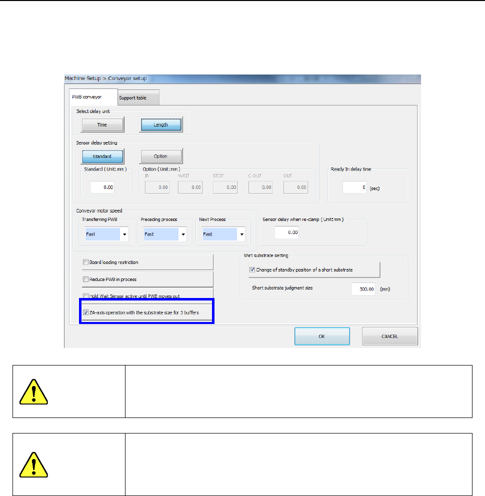
12.7.4.2 How to set (on the “Machine Setup” screen)
Select the [Conveyor setup] command, and then the “PWB conveyor” tab from the “Machine Setup”
screen to check to see if a checkmark is put in the check box “ZA-axis operation with the substrate
size for 3 buffers.”
See Section 8.3.3.1 “Conveyor setup” for how to set this item.
CAUITON
If you do not enter the board size correctly, a head may come in contact
with a component already placed on the board.
Be sure to enter the correct setting value.
CAUITON
To enable this function, check and understand the operation conditions
of the ZA-axis such as the conditions described under Section 2.14.1
“Conditions necessary to operate the ZA-axis at a 3mm-height” before
using it in the same manner as production in 1-buffer mode.
Part 2 Detailed Description of Each Function Chapter 12 Handling the Optional Devices
12-48
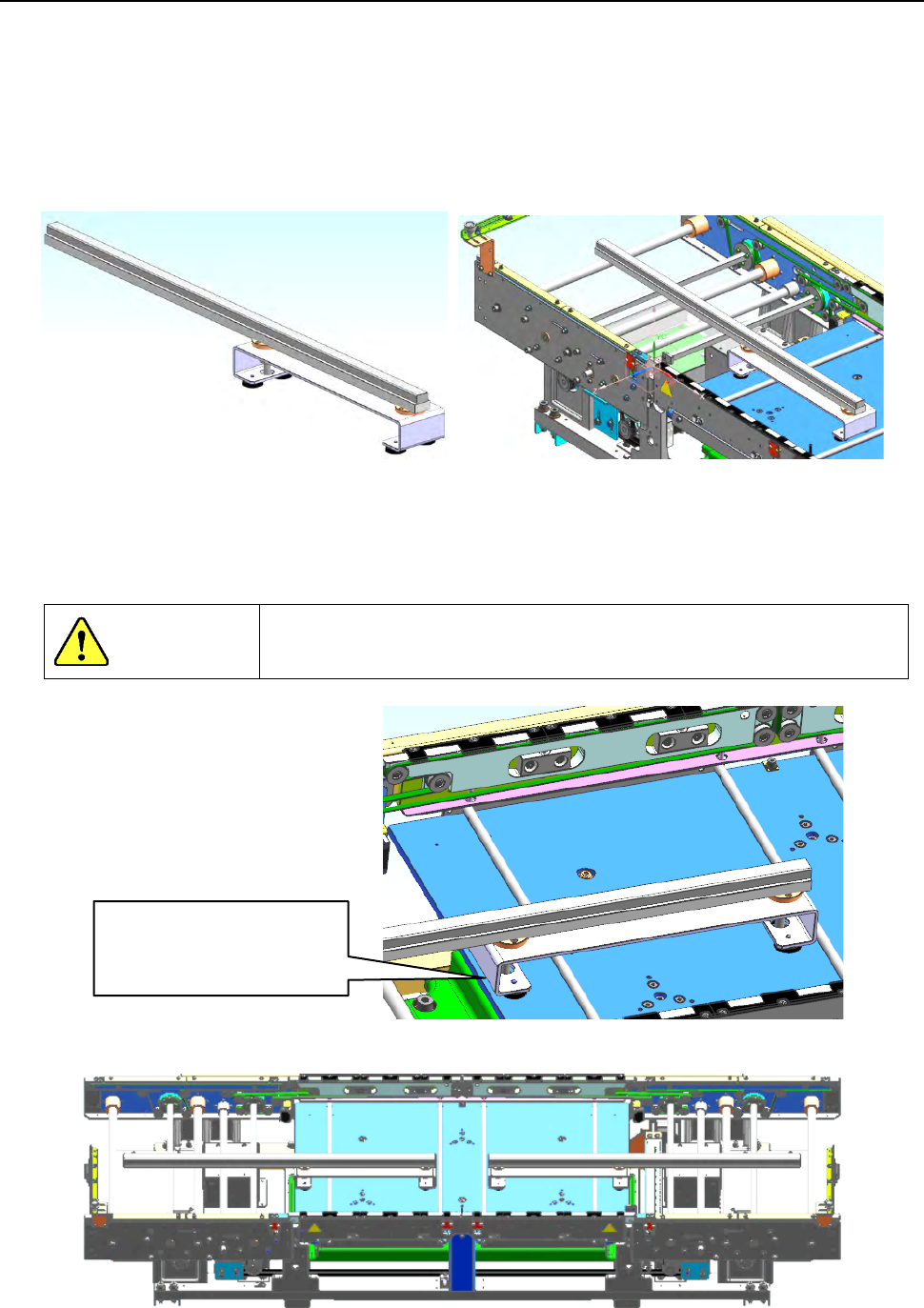
12.7.5 Sponge for Supporting a Long-sized Board
This is a part for preventing a long-sized board from flapping when unclamped, and you can
purchase it as an optional unit.
It is supposed to be installed on the support table with magnets.
* Up to two units can be installed on the machine. (Each one is installed on the IN side and the
OUT side.)
* Note that when it is installed on the machine, the space below a board should be 25 mm or more
and the minimum board width is 110 mm.)
[How to install the sponge]
When you place the sponge on the support table, be careful so that the sponge cannot protrude
from the edge of the table as shown in the figure below.
(Pay attention to the opposite side too.)
DANGER
If you operate the machine even though the sponge protrudes from the
table, it interferes with any other part, and the sponge and the part may
be damaged or deformed.
[Example: when two units are installed on the machine]
Install the sponge so that
it cannot protrude from
the edge of the table.
Part 2 Detailed Description of Each Function Chapter 12 Handling the Optional Devices
12-49
12.8 How to Install a Matrix Tray Changer (MTC)
For this machine, the MTS is selectable from between the TR6SNV and the TR6DNV.
Refer to the MTC Instruction Manual for details on handling and setting.
To install onto an RS-1/1R a TR6SNV or a TR6DNV that was installed on another machine model,
it has to be remodeled, its software has to be upgraded, and the setting of the DIP switch has to be
changed. If any of this is not performed, the system stops urgently when you turn it on.
Contact our Service department for remodeling or upgrading of the MTC.
* To use a TR6SNX or TR6DNX that has been remodeled already and whose software has been
upgraded with an RS-1/1R or another machine model, follow the instructions described in
Sections 12.7.2.
To avoid any accident caused by sudden activation of the machine,
turn off the power.
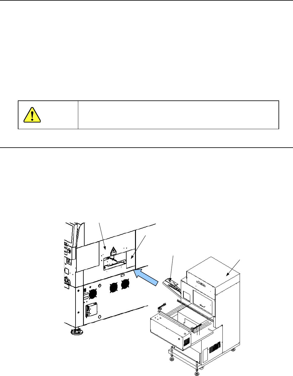
12.8.1 How to install an MTC
(1) Move the “MTC main unit 4” from the rear so that the “MTC shuttle section 3” can be inserted
into behind the “MTC guide cover 1” on the right rear side when viewed from the front of the
main unit.
(2) Check to see if the head of the mounter can move to the pick-up position of the shuttle when
the conveyor rail height is aligned with that of the reference rail.
CAUTION
①
②
③
①
MTC guide cover
② Cover RUR
③ MTC shuttle section
④ MTC main unit
④