RS-1_instruction manual.pdf - 第116页
Part 1 B asic O peration Chapter 2 Pr oduction 2-5 2.3 Star t Up and Shut Down of The Sys tem Starting up the system ( 1) T urn clockwise the “m ain switch” on t he right sid e of the front of the main unit to turn on th…
Part 1 Basic Operation Chapter 2 Production
2-4
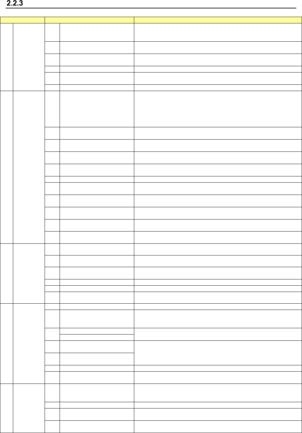
Production main menu configuration
Main menu
Pull-down menu
Description
1 File
1 Open
Loads a production program file.
See “2.6.1 Opening a file (to load a file)” of the section on the program
editing.
2 Save
Saves a program you have edited.
See “2.6.2 Saving a file” of the section on the program editing.
3 Save as
Saves a program with a new name you specified.
See “2.6.3 Saving a file with the desired name.”
4
Get and Save Machine Data
Obtains the machine information and saves it to a file.
5 Save Management Info
Outputs the production management information of a program as a text file
(*.csv).
6
Cont. prod. file Delete
Deletes a continuous production file of the production program.
2 Window
1 Prod Cond.
Displays the production start-up screen: settings you made on the PWB
production requirements /Trial requirements /Dry run requirements
/Operation Option menu.
This menu also allows you to set the conditions to be applied when you
make the common settings, or when you execute PWB production, Trial or
Dry run operation.
2
Production status
(Production condition)
This menu displays the conditions of the facility that is performing PWB
production.
3 Production (Vision)
Displays the recognized mark image and the component image recognized
with a VCS both of which were shot during PWB production.
4 Production status(Action)
This menu displays the data such as the step No. that is being used for
production also.
5 Production status(Zoom)
This menu displays the number of PWBs that are being produced in large
characters.
6
Management Info. (Total)
Displays the accumulated data unique to a production program.
7 Management Info. (Head)
Displays the accumulated data (such as the number of component pick-up
operations that have been performed) per nozzle head.
8 Management Info. (Feeder)
Displays data on each component pick-up position of a feeder (such as the
number of component pick-up operations).
9 Management Info. (Pick ratio)
Displays the PWB pick-up position of each pick-up device or displays the
pick-up rate per level in ascending order (that is, from the worst rate).
10 Electric feeder check Displays the electric feeder condition.
11 Collation Check
You can check the component collation state when you use an IFS-NX
option.
3 Program
1 Retry list (Supplier) Displays the screen showing information on component supply units.
2 Retry list (Not placed) Displays the list of components not placed.
3 Component supply
Displays the “Component supply” screen.
This menu allows you to set the number of components in each Pick data.
4
Edit data
Allows you to change a part of data.
5
Program Check
Checks a production program before start of production.
6 Management Info is cleared Clears the production management information.
4 Support
1
Plan support
Allows you to make preparations before start of production.
2 Placement tracking
Displays the list of component placement positions of a production program
before start of production, and tracks each placement position to check to
see if a component is actually placed on a board.
3
Verify Current check
Allows you to run a verify check.
Verify All check
4
GNRL. Vision direction single
inspection
A general-purpose vision component direction inspection can be made.
5
GNRL. Vision direction
continuous inspection
6
Laser check
Performs a laser height check.
7
Auto-Correct pick position
Clear
Clears information on correction of a component pick-up position.
5 Tool
1 Operation option
Displays the “Operation option” screen.
This menu allows you to make settings of operation to be done during
production.
2
Setting of displayed items
Displays/hides the items of states during PWB production.
3 IFS server reconnection
Reconnects to the IFS server without restarting the machine when you use
an IFS-NX option.
4
Event notification destination
reconnect
When using the external output function, reconnect to the notification
destination without restarting the mounter.
Part 1 Basic Operation Chapter 2 Production
2-5
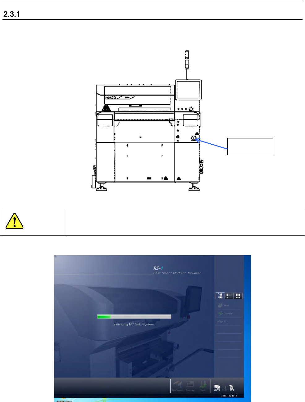
2.3 Start Up and Shut Down of The System
Starting up the system
(1) Turn clockwise the “main switch” on the right side of the front of the main unit to turn on the
machine.
CAUTION
Do not turn off the main switch until the system operation is completed.
Otherwise the SSD may be damaged
(2) Windows starts up, and then the start-up screen appears.
Main switch
Part 1 Basic Operation Chapter 2 Production
2-6
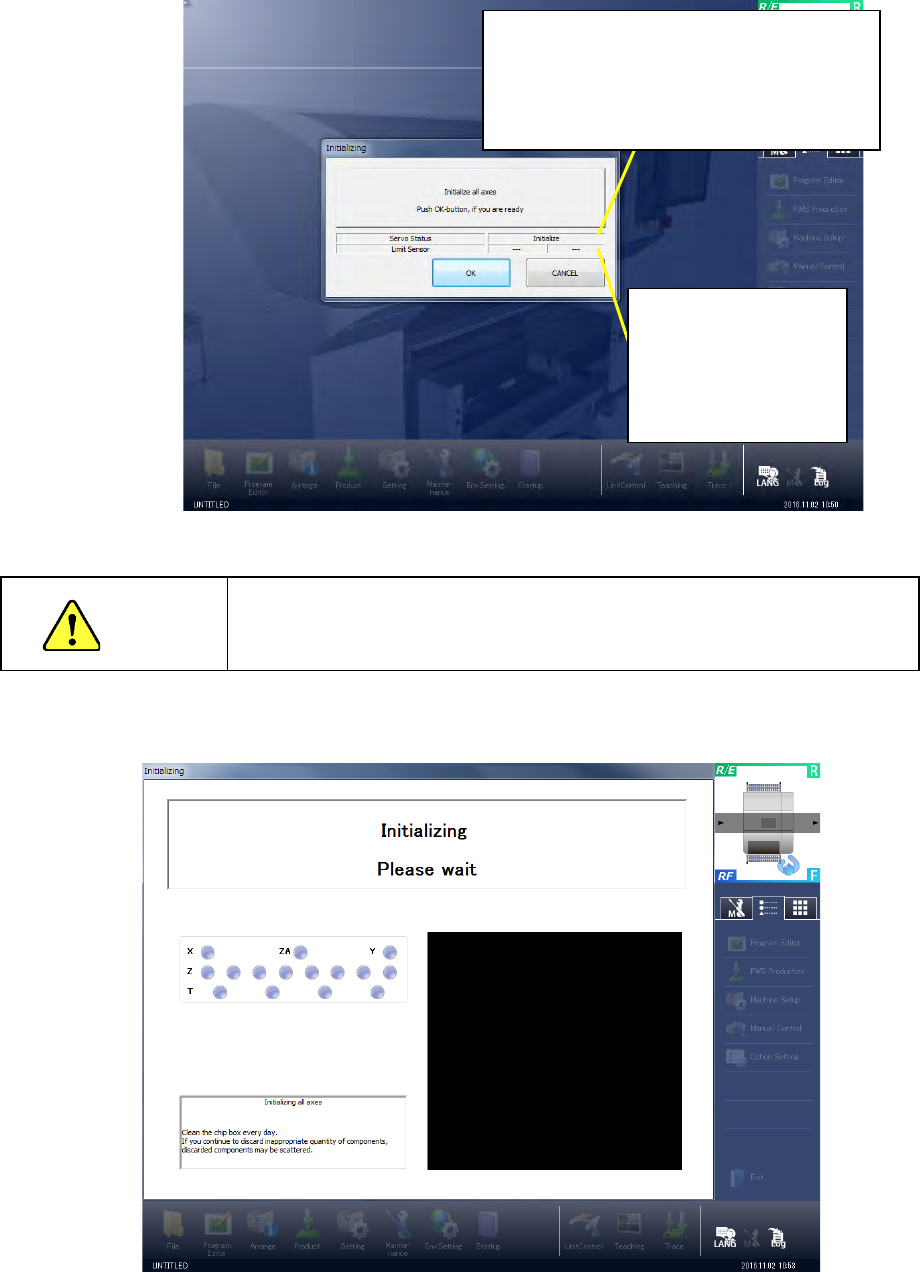
(3) When you finish making the initial settings of the system, the main screen appears, and then
the “Initialize” dialog box appears over the main screen.
When you click the <OK> button, the system executes the origin return function.
WARNING
When the system executes the origin return function, the machine
starts operating. Be sure to keep your hands or head away from the
inside of the machine to avoid injury.
(4) When the system finishes making initial settings, the mains screen appears, and then the
“Initializing” screen appears over the main screen.
Display of the servo status of all axes on the front
side
(When you have not initialized the axes: Initialize
When the servo mechanism can be set to ON:
Servo ON possible
When the servo mechanism is set to ON: OK)
Indication of limit sensor
status
When Y-axis limit sensor
is activated: Y
When X-axis limit sensor
is activated: X