RS-1_instruction manual.pdf - 第528页
Part 1 B asic O peration Chapter 4 Cr eating a Produc tion Progra m 4- 193 (1) T eaching a boar d mark T o teach a board mark, f ollow the proc edure below after teaching starts. 1) Setting t he scale frame Align the upp…
Part 1 Basic Operation Chapter 4 Creating a Production Program
4-192
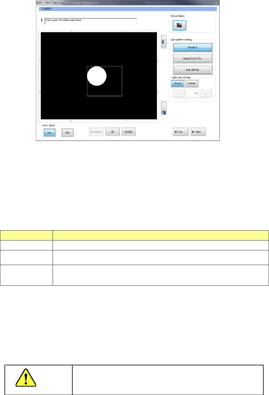
When you select the “Teaching” button, the camera moves to the XY coordinates of the entered
mark position, and then the image shot with the selected camera and the scale frame (rectangular
frame) are displayed on the screen.
1) Device Select
When you press the camera button shown in the “Device Select” column, you can reverse
the polarity (brightness).
If a mark looks black against the board, press the camera button so that the mark can look
white.
Reverse of the mark with the camera button is effective only when you enter the scale
frame.
2) Light pattern setting
If a mark can be recognized according to the standard setting of the light (that is, when the
<Standard> button is selected), you do not have to set this item.
Set this menu item only when the system does not recognize a mark stably.
Light pattern Processing
Standard
Use this button to recognize a normal board mark.
Resist/Cover Film
Use this button when the mark reflects the standard light in an undesirable manner and
a mark cannot be recognized stably because there is a resist or a cover film on a mark.
User defined
Use this button to set the light amount of the vertical light and that of the inclined light
directly when a mark reflects the light in an undesirable manner in the two cases above
and the mark cannot be recognized stably.
When you select the <User defined> button, enter the light value directly.
Select the <Vertical> button or the <Inclined> button, and then enter a value in the edit box,
or use the <+> button and/or the <-> button to change the entered value.
3) Move Speed
You can select the speed at which the camera moves.
When you touch the image shot with the camera, the XY-axes move in eight directions.
While you are touching the image, the axes continue to move.
CAUTION
To avoid a risk of injury, do not put your hands inside the machine
or move your face or head close the machine while the system is
teaching data.
Part 1 Basic Operation Chapter 4 Creating a Production Program
4-193
(1) Teaching a board mark
To teach a board mark, follow the procedure below after teaching starts.
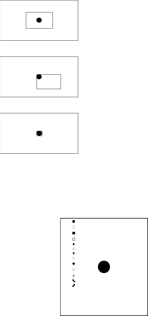
1) Setting the scale frame
Align the upper side and the left side of the scale frame with the upper edge and the
left edge of the mark, and then select the <OK> button to validate these two sides.
After validating two sides, align the lower side and the right side of the scale frame with
the lower edge and the right edge of the mark in the same manner, and then select the
<OK> button to validate these two sides.
At this point, the system automatically recognizes the mark, and obtains data
necessary for correction.
2) Setting the noise cut level
The system automatically obtains the noise cut level around the mark, and then
displays it.
Adjust the noise cut level with pressing the upper/lower sides of the frame so that the
mark can be displayed clearly and the noise around the mark can be reduced as much
as possible.
After adjustment, press the <OK> button.
[*]
[ ]
[ ]
[ ]
[ ]
[ ]
[ ]
[ ]
[ ]
[ ]
[ ]
[ ]
[ ]
[ ]PR
The image shot with the camera and the scale frame are displayed
on the screen.
First, set the upper side and the left side of the scale frame.
Adjust these sides so that they match the upper edge and the left
edge of the mark respectively.
After adjustment, press the <OK> button.
In the same manner, set the lower side and the right side of the
scale frame.
After adjustment, press the <OK> button.
Part 1 Basic Operation Chapter 4 Creating a Production Program
4-194
3) Setting the shape of a mark
After setting the noise cut level, the system automatically recognizes the shape of the
mark, and then appends a “*” mark next to the corresponding mark displayed in the list
of mark shapes on the left side of the screen.
If the system misjudges the mark shape, press the top/bottom of the frame to select
the correct mark.
When you press the <OK> button, the system allows you to go to the next step.
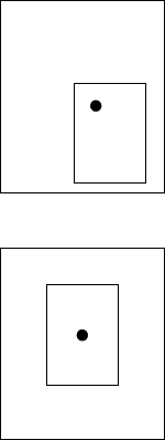
4) Setting the detection frame
Next, the system teaches the detection frame.
After the mark shape is set, the system automatically displays the window whose size
is 1.5 times as big as that of the mark so that its center can be aligned with that of the
screen.
To change the position or size of the detection frame, set it in the same manner as the
scale frame.
When you press the <Prev> button at this point, you can return to the procedure for setting
the scale frame.
Set the detection frame in the same manner as the scale frame.
See “1) Setting the scale frame” for how to set the detection frame.
S After adjustm
ent, press the <OK> button.