RS-1_instruction manual.pdf - 第180页
Part 1 B asic O peration Chapter 2 Pr oduction 2- 69 Placement data Select the “P l acement ” ta b displayed o n the top of t he screen. (1) Li st of t he menu items The menu ite ms displaye d on the left plane of t he s…
Part 1 Basic Operation Chapter 2 Production
2-68
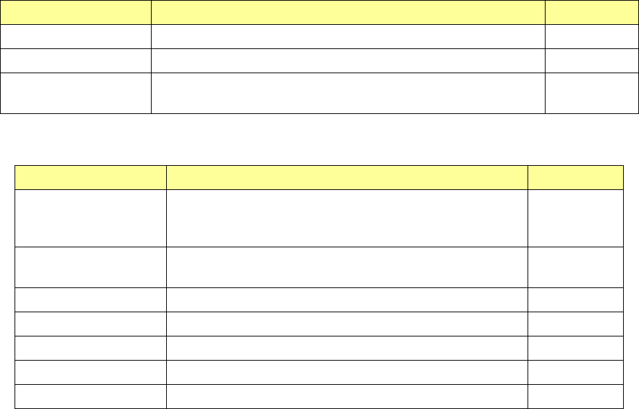
Menu item Description User level
PWB thickness Enter the thickness of a board. Programmer
Back height Enter the height of the rear side of a board. Programmer
Head height at
production start
Displays the head height at the time of production start. −
(3) PWB surface
The following table shows the contents of PWB surface settings on dimension settings.
Menu item Description User level
BOC type Displays the BOC mark type.
(“Not Used,” “PWB marks/ref. ckt marks are used,” or “Circuit
marks are used”)
−
PWB configuration Displays the circuit configuration of a board. (Single PWB,
Matrix circuit and so on)
−
Circuit dimensions Displays the outside dimensions of a circuit. −
Circuit layout offset Displays the circuit layout offset. −
First circuit position Displays the position of the first circuit on a board. −
Circuit divide No. Displays the number of circuits on a board. −
Circuit pitch Displays the distance between two consecutive circuits. −
Part 1 Basic Operation Chapter 2 Production
2-69
Placement data
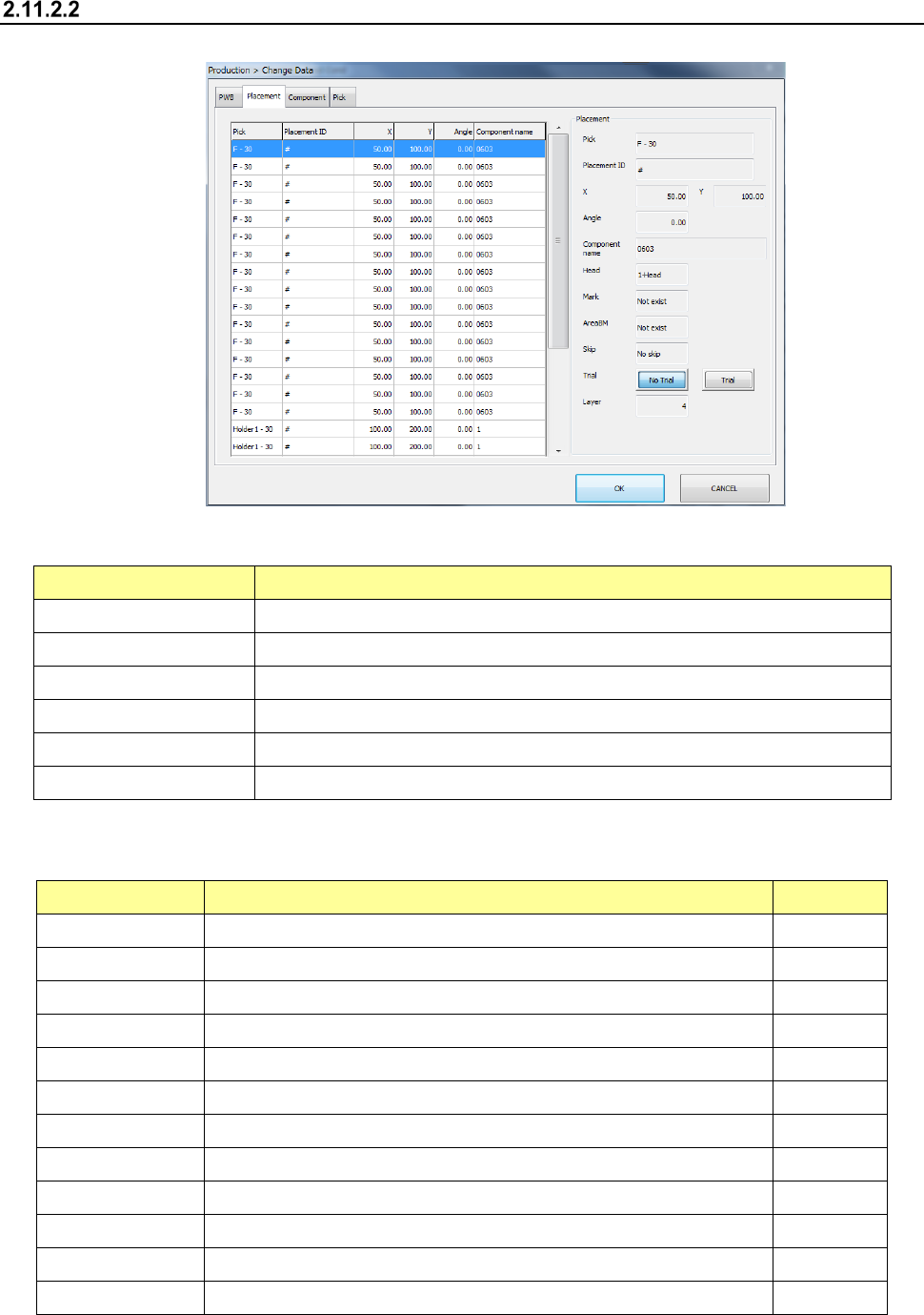
Select the “Placement” tab displayed on the top of the screen.
(1) List of the menu items
The menu items displayed on the left plane of the screen are described in the table below.
Menu item Description
Pick Displays the supply position of a component to be placed on a board.
Placement ID Displays a placement ID of the current placement operation.
X Displays an X coordinate of a component placement position.
Y Displays a Y coordinate of a component placement position.
Angle Displays the angle of a component to be placed on a board.
Component name Displays the name of a component to be placed on a board.
(2) Placement
The descriptions of the selected menu item on the left plane of the screen are displayed on the
right plane.
Menu item Description User level
Pick Displays the supply position of a component to be placed on a board.
Placement ID Displays a placement ID of the current placement operation
X Displays an X coordinate of a component placement position.
Y Displays a Y coordinate of a component placement position.
Angle Displays the angle of a component to be placed on a board.
Component name Displays the name of a component to be placed on a board
Head Displays a head to be used to place a component on a board.
Mark Displays whether to use an area mark or not.
AreaBM Displays whether to use an area bad mark or not.
Skip Allows you to select whether to skip placement operation or not. Programmer
Trial Displays whether to place a component on a board during trial operation
Layer Displays a placement layer.
Part 1 Basic Operation Chapter 2 Production
2-70
“Component” data
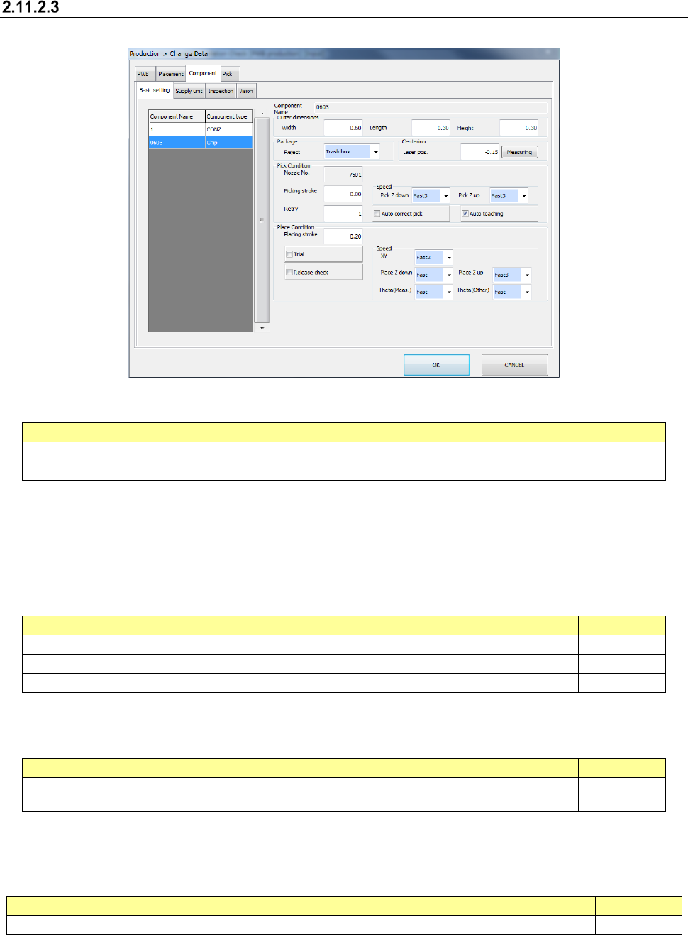
Select the “Component” tab displayed on the top of the screen.
(1) List of the displayed menu items
The menu items displayed on the left plane of the screen are described in the table below.
Menu item
Description
Component Name
Displays a component name.
Component type
Displays a component type.
(2) Component Name
The component name is displayed here.
(3) Outer dimensions
This menu item allows you to display and/or edit the outer dimensions of a component.
Menu item
Description
User level
Width
Enter the width of the outer dimensions of a component.
Operator
Length
Enter the length of the outer dimensions of a component.
Operator
Height
Displays the height of the outer dimensions of a component.
Operator
(4) Package
This menu item allows you to display and/or edit where to discard a component.
Menu item
Description
User level
Reject Select how to discard a component. Operator
(5) Centering
This menu item allows you to display/edit the height of laser to be used for a component. The
contents vary depending on each model.
Menu item
Description
User level
Laser pos.
Enter the laser height of a component. You can measure the laser height also.
Operator