RS-1_instruction manual.pdf - 第202页
Part 1 B asic O peration Chapter 2 Pr oduction 2- 91 ( 3) Execution of t racking of a com ponent p ick - up po siti on When you pres s the <OK> butt on to start cor recting a com ponent pi ck - up pos ition, the “P…
Part 1 Basic Operation Chapter 2 Production
2-90
Pick position correction
(1) Overview
When you press the “Trace” button displayed in the Operation area while the “Retry list” is
displayed on the screen, the “Pick pos. adjust conditions” screen appears.
You can track a component pick-up position under the conditions specified on this screen to
correct the component pick-up position.
Components whose pick-up position is corrected are automatically replenished.
What to correct varies depending on the displayed data on the “Retry list” you invoked:
♦ When the “Retry list (Supplier)” appears
The system corrects a component pick-up position of the displayed component supply unit.
♦ When the “Retry list (Not placed)” appears
The system corrects pick-up positions of component supply units assigned to all unplaced
components.
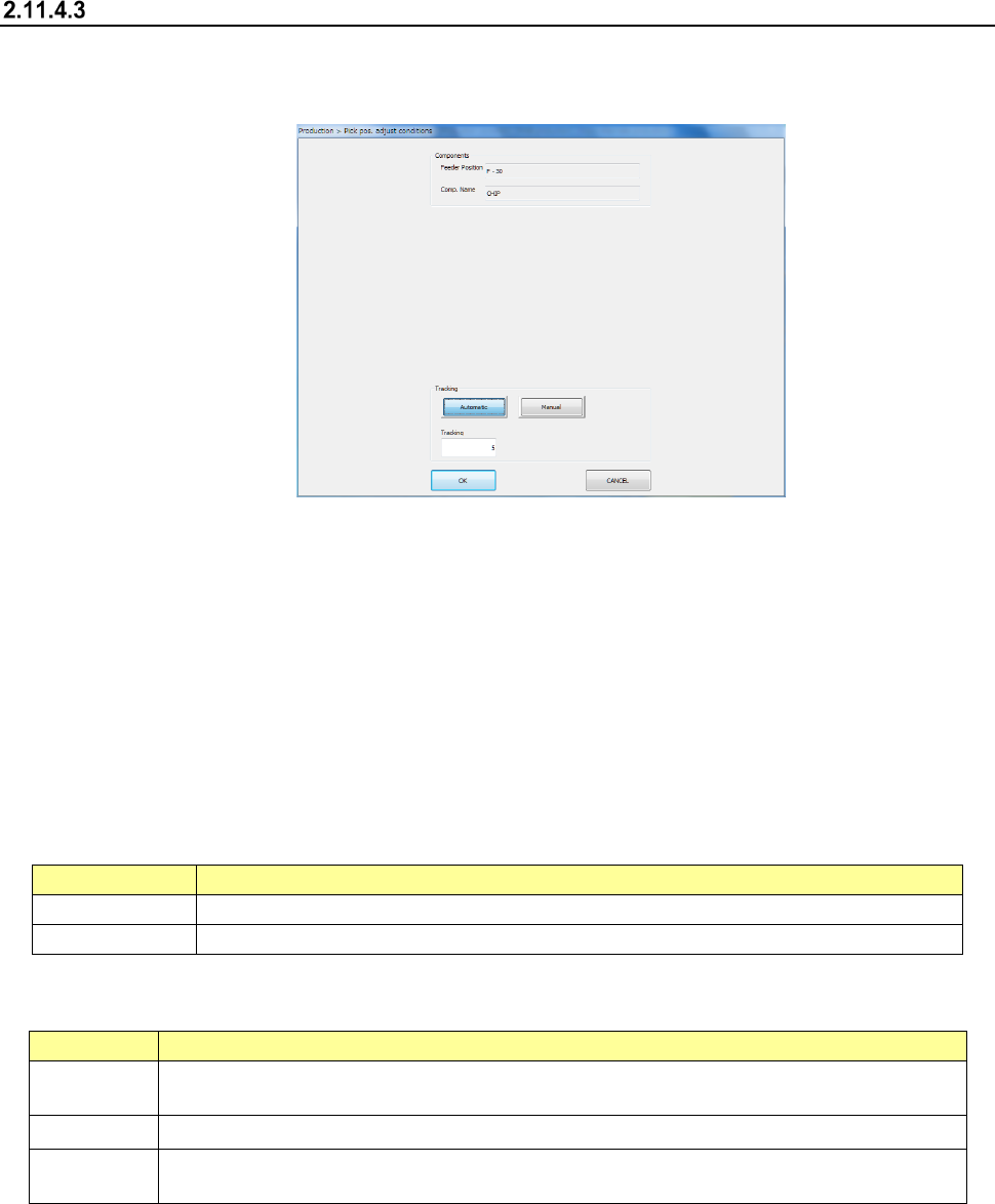
(2) Displaying the conditions for correcting the component pick-up position
1) Components
The pick-up position and name of a component to be corrected appear here.
Menu item
Description
Feeder Position
Displays the component pick-up position to be corrected.
Comp. Name
Displays the name of a component whose pick-up position is to be corrected.
2) Tracking
How to track a component pick-up position to be corrected appears here.
Menu item
Description
Automatic
The system stops at a component pick-up position for the certain time after correcting it, and
automatically moves to the next pick-up position.
Tracking
Specify the time period while the system has to stop when you select “Automatic” above.
Manual
The system pauses for the certain time after correcting the component pick-up position. The
system corrects the next pick-up point according to the operator’s input.
3) <OK> button and <CANCEL> button
When you press the <OK> button, the system tracks a component pick-up position, and
corrects it. Details of this operation are described in the next section.
When you press the <CANCEL> button, the system finishes correcting a component
pick-up position.
Part 1 Basic Operation Chapter 2 Production
2-91
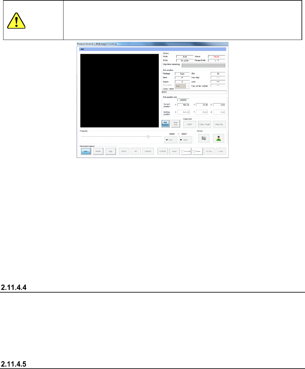
(3) Execution of tracking of a component pick-up position
When you press the <OK> button to start correcting a component pick-up position, the “Pick
position tracking” dialog box appears on the screen.
See Section 4.5.6.5 “Pick position/Pick height” of Chapter 4 “Creating a Production Program” or
Section 2.14.6 “Tracking a component pick-up position with a camera” for details of the
displayed data.
CAUTION
If the feeder bank is never recognized (for example, immediately after the devices of the
machine return to their home positions or the bank moves down then up), the feeder may be
recognized automatically before the machine moves to the pick-up position. Since the
head moves across the feeder bank while the feeder is being recognized, do not place your
hand or head in the machine, nor move your hand or face close to the machine.
1) When you select <Automatic> of the “Tracking” buttons
Before the system starts placing a component on a board, the camera moves to the first
component pick-up position, and displays the monitored image on the screen.
The camera stops at this position for the time specified in the “Tracking” field, and then
automatically moves to the next pick-up position.
To quit this automatic tracking operation for correcting a component pick-up position, press the
<STOP> switch of the operation panel. If you press the <STOP> button when the system
pauses, the camera stops at the current pick-up position. If you do when the camera is moving
to the next pick-up position, it stops at the next pick-up position.
2) When you select <Manual> of the “Tracking” buttons
After the system corrects the first pick-up position, it finishes tracking a pick-up position.
When you press the <START> button on Pick-up Position Correction mode, the system corrects
the next component pick-up position.
Teaching during tracking of a component pick-up position
If the tracked component pick-up position is found to be different from the actual pick-up position as
result of tracking described in the previous section, you can teach the component pick-up position
also.
When you press the displayed image on the touch panel: the upper, lower, left or right position,
you can change the current pick-up position. When you teach the coordinates and validate the
position, you can change the pick-up position set in the Pick data. Perform auto-teaching to
recognize the cavity for a component to be taught automatically.
Teaching the pick-up position
Select a feeder whose component pick-up position you want to teach when the “Retry list (Supplier)
is displayed on the screen, and then press the <Teaching> button displayed in the Operation area.
The system teaches the component pick-up position also.
Part 1 Basic Operation Chapter 2 Production
2-92
2.12 Support
This command performs various types of checking operations before the system starts PWB
production.
Plan support
Overview
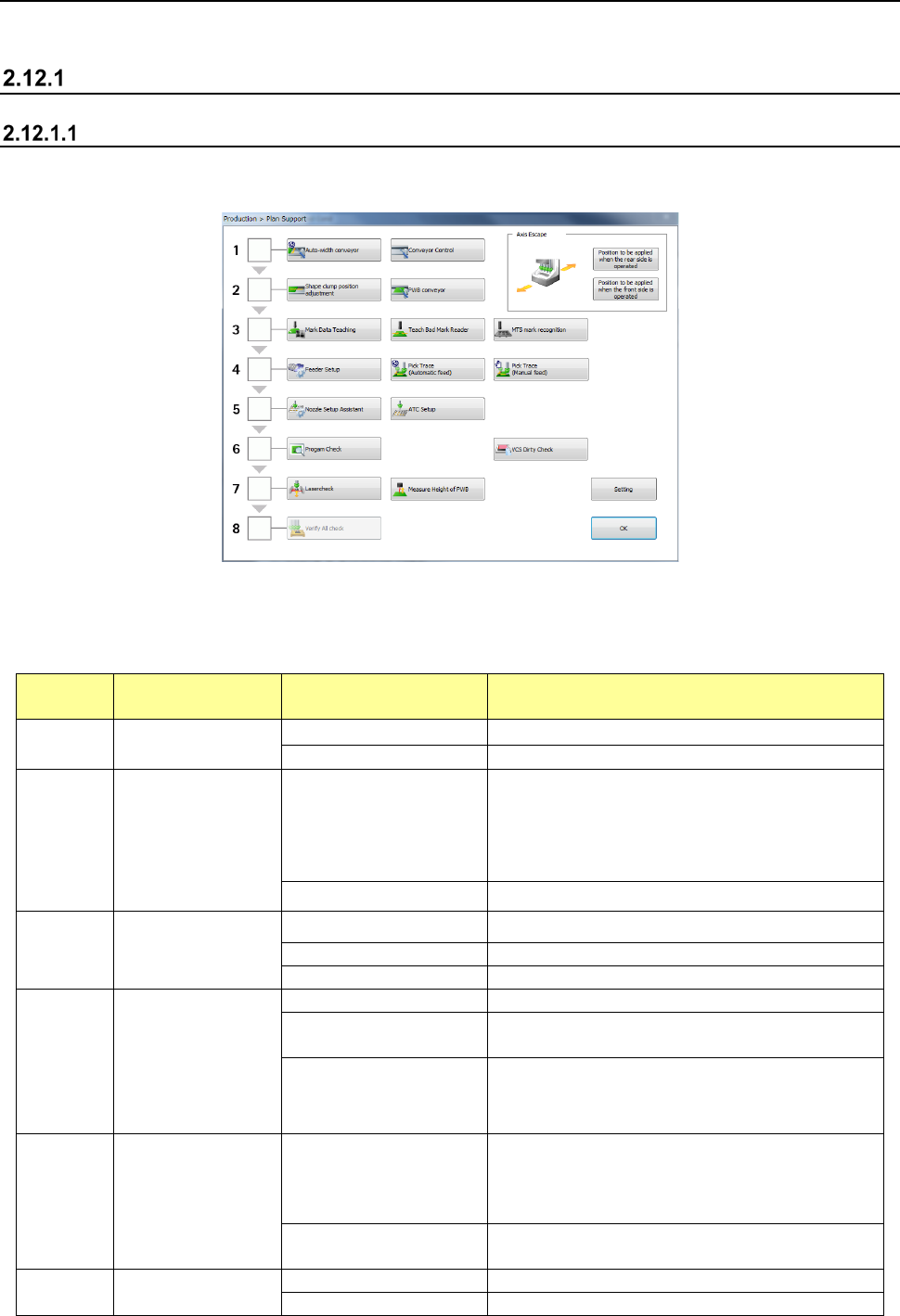
When you select the [Support] command from the “Product” menu, and then the [Plan support]
command, the “Plan Support” screen appears.
(1) Planning
When you perform the operation steps shown below from “1. Adjustment of the conveyor
width” to “8. Check of component supply” sequentially to finish all preparations, the system
gets ready for PWB production completely.
Operation
step
What to prepare Detailed operation Description
1
Adjustment of the
conveyor width
Auto-width conveyor
Adjusts the conveyor width.
Conveyor Control
Controls board transport operation.
2 Board transport
Shape clamp position
Teaches the board stop position.
When the machine transports a board without any
stopper, it adjusts the board stop position. When
the machine transports a board with the stopper, it
adjusts the shape clamp reference position.
PWB conveyor
Transports a board.
3 Teaching of a mark
Mark Data Teaching Sets a BOC mark and an area fiducial mark.
Teach Bad Mark Reader
Teaches a bad mark.
MTS mark recognition
Recognizes an MTS mark.
4 Feeder Setup
Feeder Setup
Teaches a feeder attached on each bank.
Pick Trace
(Automatic feed)
Tracks a component pick-up position (with feeding
automatically).
Pick Trace (Manual feed)
Tracks a component pick-up position (with feeding
manually).
5 Nozzle setup
Nozzle Setup Assistant
Compares the nozzle assignment of the ATC
specified in a production program with the actual
assignment, and if there is any difference between
them, displays it.
ATC Setup
Automatically assigns a nozzle from the ATC to the
selected hole number.
6
Check before start
of PWB production
Program Check
Performs a production program check.
VCS Dirty Check
Perform VCS dirt check and display the result.