RS-1_instruction manual.pdf - 第133页
Part 1 B asic O peration Chapter 2 Pr oduction 2- 22 2.7 Prepa ration for PWB Production Setting up a PWB <Procedur e> How t o set up each P WB production mo de on the “Pl an Suppor t” screen *1 i nvoked from the “…
Part 1 Basic Operation Chapter 2 Production
2-21
Saving a file
This function saves production program and Management Information by overwriting it.
Click the “File” button on the menu, and then the [Save] command.
The program is saved.
CAUTION
When you save a production program, the original contents are erased.
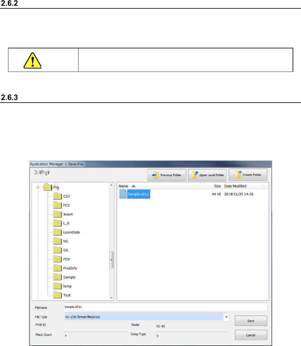
Saving a file with the desired name
Select the [Save as] command to save the edited production program in another folder or with a
new name you specify.
① Click the “File” button, and then the [Save as] command.
② Specify the desired folder and file name on the “Save File” screen, and click the <Save>
button.

Part 1 Basic Operation Chapter 2 Production
2-22
2.7 Preparation for PWB Production
Setting up a PWB
<Procedure>
How to set up each PWB production mode on the “Plan Support” screen *1 invoked from the
“Production” screen is described here.
The operations described below become available only after you start up the Production utility
unless otherwise noted.
*1 “Plan Support” screen invoked from the “Product” menu: When you select the [Support]
command from the menu invoked with the “Product” button of the main menu, and then the
[Plan Support] command, you can execute the function for selecting a check or adjustment to
be performed at preparation stage of PWB production by selecting the corresponding menu on
the “Production” screen. This improves the operability of the system.
See Section 4.5.2.5 “Transport” for the detailed description of transport of a PWB.
See Section 2.12.1 “Plan support” for the detailed descriptions of the plan support functions.
Note: You have to load a production program to the system in order to start up the Production
utility.
Positioning of the support pin
Adjustment of the PWB transport rail width
Part 1 Basic Operation Chapter 2 Production
2-23
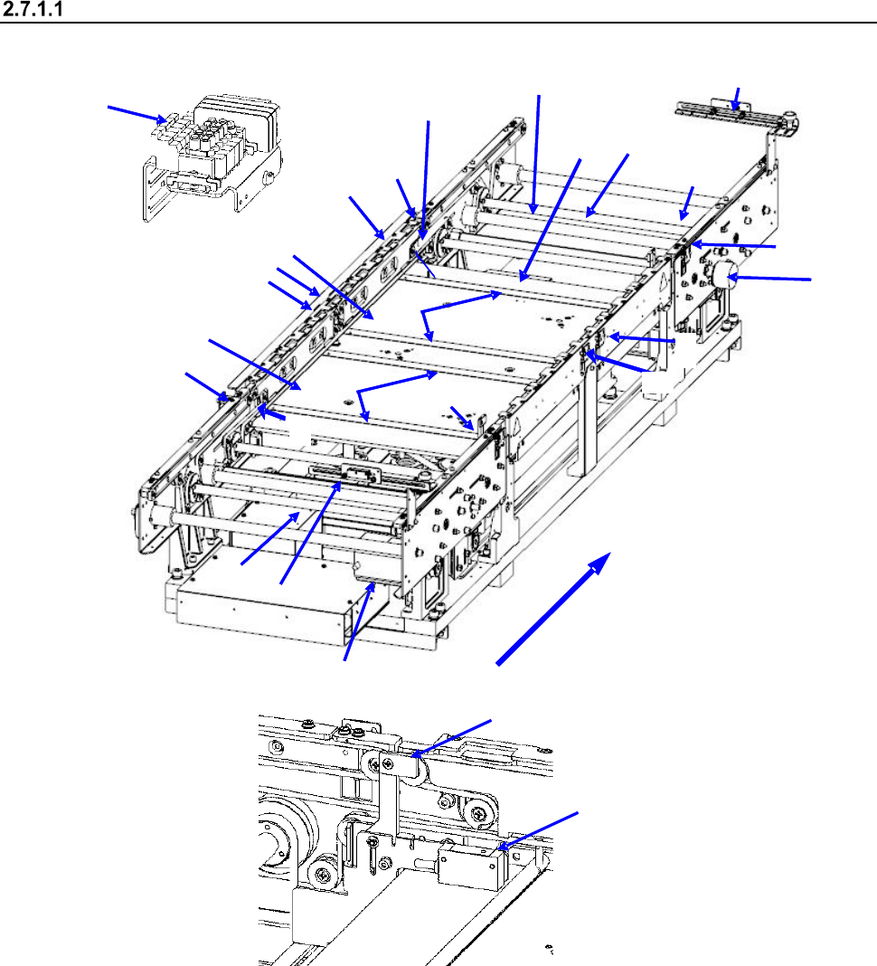
Configuration of the PWB transport unit
<Name of each part of the conveyor (PWB transport unit)>
2
1
15
11
3
4
8
10
11
12
10
13
14
17
16
18
11
7
5
9
12
6
21
20
22
23
Board transfer direction
1 IN sensor
9 Board transport electromagnetic
valve
17 Support pin detection sensor light receiving
section
2 OUTsensor
10 Conveyor motor
18 Stopper sensor
3 WAIT sensor fiber light receiving section
11 Drive shaft
19 Stopper
4 WAIT sensor fiber light emitting section
12 Side beam
20 (WAIT2 sensor fiber light receiving section)
5 C-OUT sensor fiber light receiving section
13 Support table IN
21 (WAIT2 sensor fiber light emitting section)
6 C-OUT sensor fiber light emitting section
14 Support table OUT
22 (WAIT2 sensor fiber light receiving section)
7 PWB guide
15 Automatic width adjustment motor
23 (WAIT2 sensor fiber light emitting section)
8 Support table origin sensor
16 Support pin detection sensor light
emitting section
18
19