RS-1_instruction manual.pdf - 第633页
Pa r t 2 D et ai l ed Des c r i pt i o n of Ea c h F unc t i o n Chapte r 6 G e neral - Purpose Vision Co mpone nt 6-2 Specifica tions of a g ener al - purpo se v ision c ompon ent 6.1.2 (1) Quanti t y - U p t o 20 elem …
Part 2 Detailed Description of Each Function Chapter 6 General-Purpose Vision Component
6-1
Chapter 6 General-Purpose Vision Component
General-Purpose Vision Components 6.1
Overview of a general-purpose vision component 6.1.1
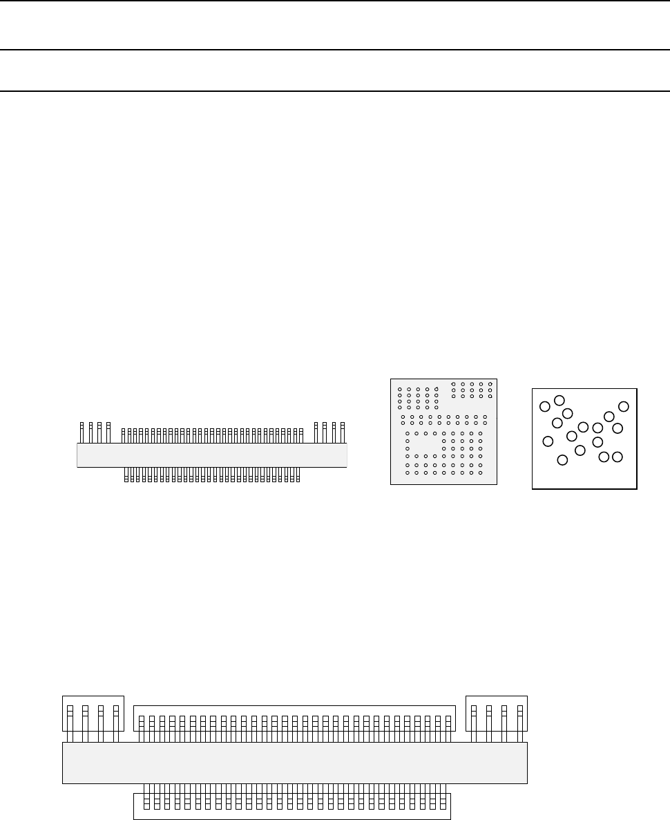
The following types of components are handled as a general-purpose vision component
- Components having multi-pitch leads, components having various sized leads, and
components having leads at not-regulated positions (these components are called
“multi-lead” components.)
- Area array components having two or more arrays (called “complex array components.)
- Components having balls/lands on not-regulated positions (called “random component”.)
- Components having a side or corner (outline-recognition components)
• The components above are classified into the following sub-component types:
− Multi-lead component: Lead component group
− Complex array component and random array components: Ball component group
− Outline-recognition component: Outline-recognition component group
A group of the same recognition elements is called an “element group.” In other words, an
element indicates a lead or a ball, and an element group indicates a group of elements of the
same size (leads or balls).
For a general-purpose vision component, a group of elements that are arranged in the same
manner is handled as one element group. By defining each element group, the system can
obtain the center of the component. A general-purpose vision component shown in Figure
consists of four element groups.
ボール部品類(複合アレイ部品
)
リード部品類(マルチリード部品)
Ball component group
(Complex array component)
Lead component group (Multi-lead component)
トップビュー
Fourth element group
Third element group
Second element group
First element group
Top view
Top view
Bottom view
ランダム配置部品
Random component
Part 2 Detailed Description of Each Function Chapter 6 General-Purpose Vision Component
6-2
Specifications of a general-purpose vision component 6.1.2
(1) Quantity
- Up to 20 element groups can be defined per component.
- Only one element can be specified per element group.
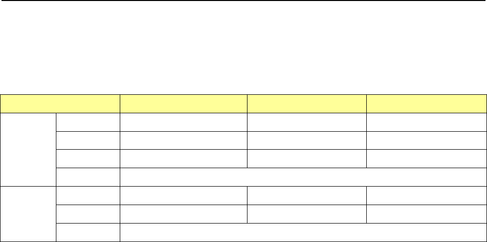
(2) Dimensions
Component type
54mm view camera
27mm view camera
10mm view camera
Lead
Pitch
0.50 to 22.0mm
0.3 to 11.0mm
0.2 to 4.00mm
Width
0.22 to 10.00mm
0.12 to 5.00mm
0.12 to 1.80mm
Length
0.40 to 10.00mm
0.20 to 5.00mm
0.20 to 1.80mm
Number
1 to 384pcs / 1 element group
Ball
Pitch
1.00 to 22.0mm
0.25 to 11.0mm
0.10 to 4.00mm
Diameter
0.40 to 5.00mm
0.10 to 2.50mm
0.04 to 0.20mm
Number
3 to 6936pcs / 1 element group
(3) Shape and size specifications of an outline-recognition component group
- The specifications of the corner/side shape are the same as those of the
outline-recognition component group.
(See “*Recognizing conditions for outline recognition components” of Section 4.3.5.2
(12) “Vision data” 13) “Outline-recognized component.”)
- A filled circle and square marks can be used.
A mark whose size is from 2 mm to 10 mm can be recognized with the VCS (54mm
view).
Part 2 Detailed Description of Each Function Chapter 6 General-Purpose Vision Component
6-3
Procedure for Creating Data on a General-Purpose Vision Component 6.1.3
To create data on a general-purpose vision component, create data on each element group.
To create data on each element group, enter:
① Element information (such as whether an element is a lead or a ball, and size and shape of an
element)
② Number of elements and pitch between two consecutive elements
③ Distance between the component recognition center and the first element*
* The first element is defined as shown below:
− For a ball component: the first element is a ball located at the bottom left corner of an element group.
− For a lead component: the first element on the bottom side is located at the leftmost position, that on the
right side is located at the lowest position, that on the top side is located at the rightmost position, and that
on the left side is located at the top position.
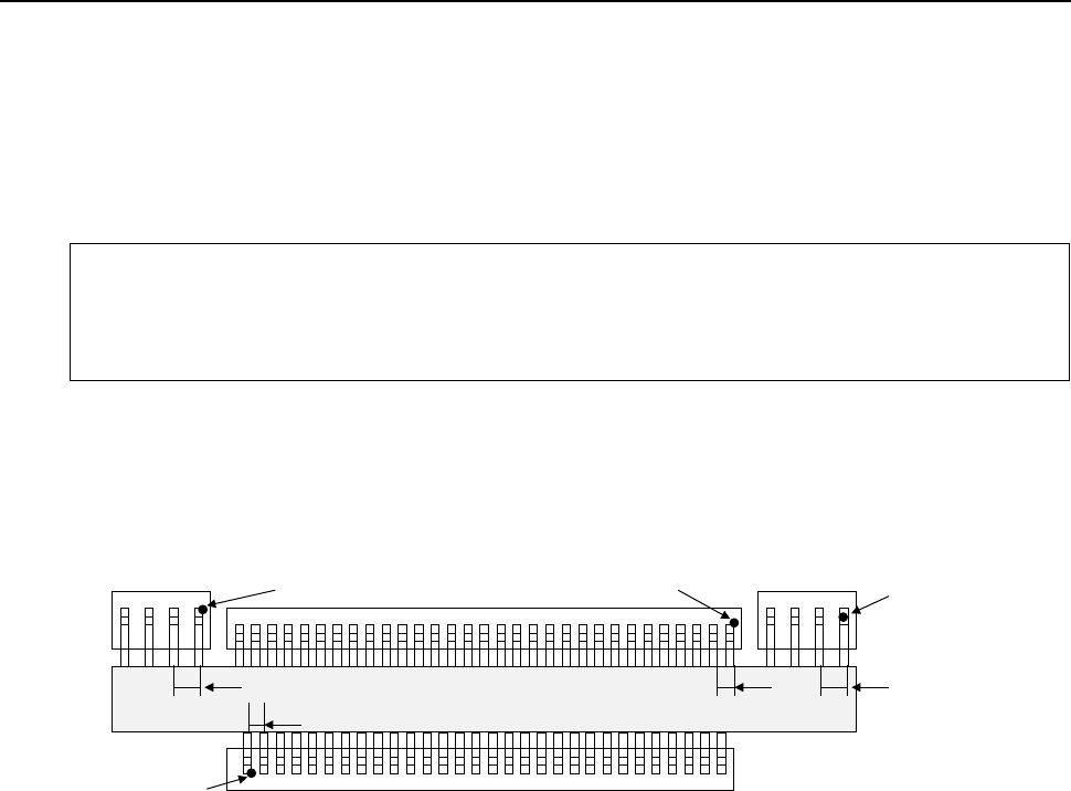
Example: For the following general-purpose component, create data on four element groups (in
mm).
How to enter “1 Element information” is not described here. See the next page for
the detail on how to enter data.
• First element group
− Number of elements and pitch between two consecutive elements ⇒
Number: 30, Pitch: 1
− Distance of the center of a component to be recognized to the first element ⇒
X: - 14.5, Y: -4
• Second element group
− Number of elements and pitch between two consecutive elements ⇒
Number: 4, Pitch: 1.5
− Distance of the center of a component to be recognized to the first element ⇒
X: 21.5, Y: 4
• Third element group
− Number of elements and pitch between two consecutive elements ⇒
Number: 31, − Pitch: 1
− Distance of the center of a component to be recognized to the first element ⇒
X: 15, Y: 4
• Fourth element group
− Number of elements and pitch between two consecutive elements ⇒
Number: 4, − Pitch: 1.5
− Distance of the center of a component to be recognized to the first element ⇒
X: - 17, Y: 4
When you enter information described above, data on a general-purpose vision component is
created completely.
Fourth element group
Third element group
Second element group
First element group
+ Center of a component to
be recognized (0, 0)
* Numeric values in
parentheses indicate the
distance from the center of a
component to be recognized.
1
(-17.4)
(-114.5, -4)
(15.4)
1.5 1.5
1
(21.5,4)