RS-1_instruction manual.pdf - 第675页
Pa r t 2 D et ai l ed Des c r i pt i o n of Ea c h F unc t i o n Chapte r 6 G e neral - Purpose Vision Co mpone nt 6- 44 - I f you sp ec if y onl y li mi ted b all s of one b all group , w e cannot guar a nte e their r e…
Part 2 Detailed Description of Each Function Chapter 6 General-Purpose Vision Component
6-43
W1
W2
L
<TOP VIEW>
W1: Pitch of Element group 1
PW2: Pitch of Element group 2
L: Distance between two element groups in
the longitudinal direction
L ≧ W1, ≧ W2 and L ≧ 1 mm
- In any case: if you define all lead groups or if you define only certain groups to recognize
them, you have to follow the two requirements described just above.
- For a connector on which two types of leads are arranged alternatively: long one and short
one, you can define two groups: a group of long leads and that of short leads. You can
define these lead groups even though they overlap one another if leads themselves do not
overlap each other. The requirements on the lead distance described above are not applied
to these lead groups unless bent leads of the different groups do not overlap.
<TOP VIEW>
First element group
Second element group
Pitch 1
Pitch 2
- If you specify only the limited leads of one lead group, we cannot guarantee their recognition
precision.
- You cannot define one lead for two different groups. You cannot define leads that overlap
each other. Note that you happen to define leads in these ways if you set the wrong lead
pitch, number of leads and/or lead width.
- You cannot specify an inner lead as the lead element type. If you specify in this way, we
cannot guarantee the recognition precision.
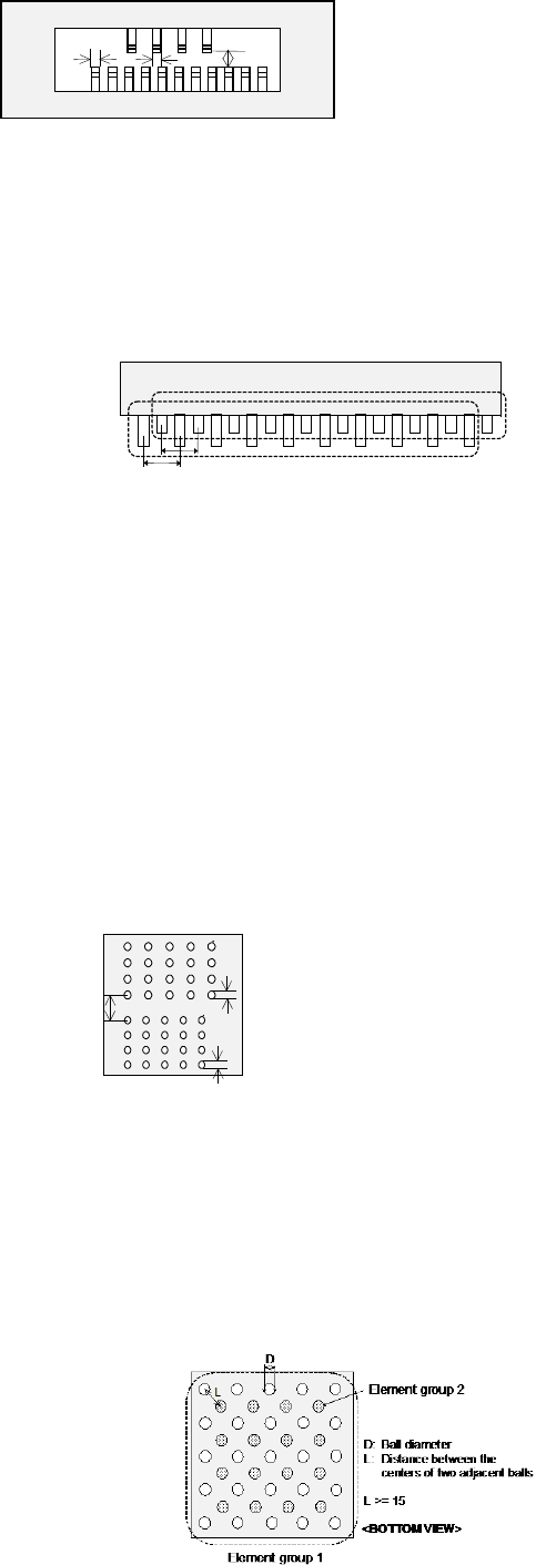
4. Ball components
- At least one ball group consisting of three or more balls of the same size should exist on a
component.
- When the similar size of ball/land groups (the diameter ratio should be less than 1.5) are
located closely, the center of one group should be far from that of another group by 2 times of
the ball/land diameter or more.
L
D1
D2
D1: Ball diameter of Element group 1
D2: Ball diameter of Element group 2
L: Distance between the centers of the two
adjacent balls
When D1 < 1.5D2 or D2 < 1.5D1,
L ≧ 2D1 and L ≧ 2D2
<BOTTOM VIEW>
- In any case: if you define all ball groups or if you define only certain groups to recognize
them, you have to follow the requirement described above.
- For a staggered type of BGA, you can define it as two square-grid ball groups. In this case,
you can specify these two groups even though these ball groups overlap one another.
However, any ball of these groups should not overlap with each other, and the centers of two
adjacent balls of each group should be located far from on another by 1.5 times of their
diameters.

Part 2 Detailed Description of Each Function Chapter 6 General-Purpose Vision Component
6-44
- If you specify only limited balls of one ball group, we cannot guarantee their recognition
accuracy.
- If the diameter check precision is the diameter ± 50 % or less, the recognizable pitch and
recognizable ball diameter are limited greatly.
- A rectangular land should be a square. (Note that the machine may recognize an element
as a lead if the ratio of the lead width to the lead length of a rectangular land is 1 : 1 or less.)
- You cannot define a ball for two different ball groups. You cannot define balls that overlap
each other either. Note that you happen to define balls in these ways if you set the wrong
ball pitch, number of ball lines and/or ball diameter.
5. Outline-recognized components
- If you define an outline-recognized component with only one type of element (corner, side or
mark) other than a lead and ball, you have to specify two or more corresponding elements. If
you specify another type of element also, you only have to specify one corresponding element
(excluding a side).
- Up to four corners can be specified for this type of component. Note that you cannot specify
two or more corners whose specified angle is the same (theta offset).
ー
θ270°
Corner
θ0°
Corner2
θ0°
Corner1
θ90°
Corner
θ180°
Corner
Although there are two corners
whose theta angle is 0 degrees, you
can specify just one corner of them.
<TOP VIEW>
- If another corner or an element (lead, rectangular land or rectangular mark) having a corner
whose angle is the same is located near one corner element, they should be far from one
another by 4 mm or more provided that the VCS (54mm view) is used.
- Up to four sides can be specified per component. However, note that two or more sides
whose specified angle is the same (theta offset) cannot be specified per component. A side
should be located on the outer frame, and its length should be half or longer of the dimension
of the component. When you specify a side (sides) only as an element, include two sides
that are orthogonal to one another.
- The linear part of the setting element should be 4.0 (±2.0 mm) or more calculated in terms of
VCS (54mm view).
- When the inside of a part is black, the thickness of the side portion should be 0.3 mm or more.
- Up to three marks can be specified per component.
- You can specify a hole as a circle mark of the reverse polarity (dark). In this case, it has to
be displayed as a circle clearly on the screen. (Note that a hole may not be displayed as a
circle clearly on the screen when a thick component is to be recognized with the perspective
light.)
- A mark should be located far from a similar-sized mark or similar-shaped and similar-sized
element (ball or circular land) by 5 mm or more provided that the VCS (54mm view) is used.
6. Notes when a general-purpose vision component data format is used
- Use this format for an element group (especially lead element group) whose positioning
precision is sufficient to be recognized. When you use this format for an element group
(especially lead element group) whose positioning precision is uncertain, a recognition error
may occur frequently.
Part 2 Detailed Description of Each Function Chapter 7 Operation Option
7-1
Chapter 7 Operation Option
7.1 Overview
When you select the [Options] command from the pull-down menu displayed after you start up the
“Operation option” utility, and then select the [Operation option] command, or when you select the
[Tool] command from the pull-own menu of the “Production” utility, and then select, the [Operation
option] command, the “Teaching” tab of the “Operation option” setting screen appears.
This utility allows you to set the operation conditions applied to data creation or production.
The items to be set as the operation options are shown in the table below.
No. Operation option group Option items
1 General
Explorer restricting function
Disable operation panel switches with the cover opened.
Data holding function at the end of system operation
2 Image (Teaching)
BOC alignment
Digital zoom
Use x4 zoom.
Auto teaching
Check the simultaneous pick enable range.
Do not perform auto teaching of pick height.
Mark auto teaching function
Upper limit value of mark size
Lower limit value of mark size
3 Image (Mark recognition)
Feeder bank recognition
Auto change of the threshold value of BOC mark
Lower limit value of the auto change of BOC recognition threshold value
Placement on the placement coordinates ignoring a solder recognition error.
4
Image (Mark recognizing
operation)
Prior recognition of BOC mark
Optimization of a BOC mark on each circuit
5 Production (Display)
Subtract the number of production PWBs.
Add the number of production PWBs.
Display the production screen by selecting Production Start (ONLINE).
Make no inquiry about storage at the end of production.
At non-stop production, “Non-stop production is not performed” is specified as the
default.
At non-stop production, “Production after re-clamp” is specified as the default.
At non-non-stop production, “Production after PWB inlet conveying” is specified as
the default.
Include “no components” in the number of pick errors.
Display a pick error at the start of production.
Subdivide errors at a temporary stop due to “no components.”
Worst feeder display method during production.
No output (Information of Coplanarity)
Only error electrode information (Information of Coplanarity)
All electrode information (Information of Coplanarity)
6 Production (Function)
Perform non-stop production at interruption of production.
Finish production when every circuit is provided with a bad mark.
Ignore transportation at dry run.
Control the residual number of components.
Consider the same component as an alternative feeder.
A vacuum check will not be run before production starts.
Operation at a cycle stop
Placing order of multiple circuits