RS-1_instruction manual.pdf - 第470页
Part 1 B asic O peration Chapter 4 Cr eating a Produc tion Progra m 4- 135 <Priority of layers> The relation bet ween layers is sho w n in the tab le below . Priority Layer type 1 Pla ceme nt lay er 2 Component la …
Part 1 Basic Operation Chapter 4 Creating a Production Program
4-134
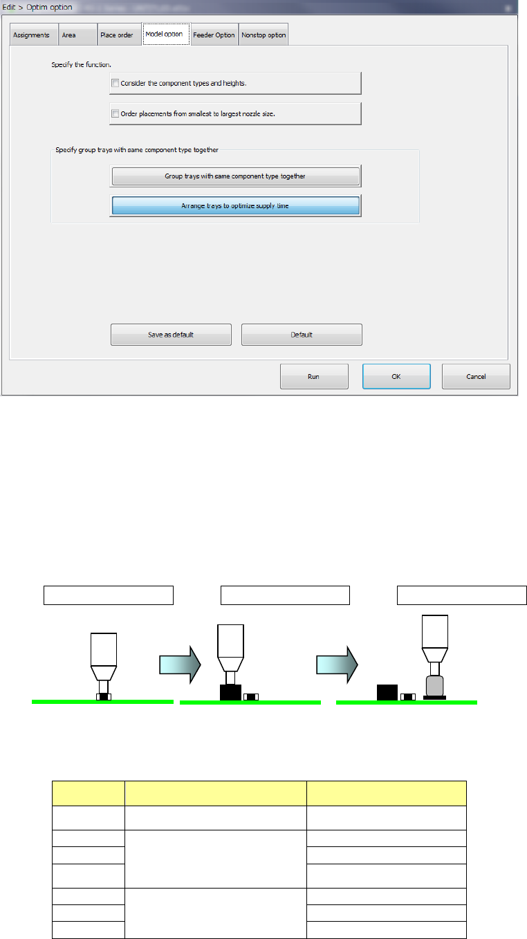
(4) Model option
1) Consider the component types and heights
When you check this check box, the system specifies the component layer with considering
the component height automatically to create a program that places components in high
density (that is, places components adjacently).
When you check this check box actually, the system places components in the following
order:
<Component placement by considering the component type and component height>
Placement order ① Placement order ② Placement order ③
<Relation between the component placement priority and the component type and height>
As indicated with “Priority” in the table below, components other than aluminum electrolytic
capacitor is prioritized.
Priority Component type Component height (mm)
1 Square chip resistor
0 < t ≦ 0.25
2
Square chip resistor
Components other than Elec.
Cap. (aluminum electrolytic
capacitor)
0
<
t
≦
5.5
3
5.5
<
t
≦
12.0
4
12.0 < t
5
Elec. Cap. (aluminum
electrolytic capacitor)
0
<
t
≦
5.5
6
5.5
<
t
≦
12.0
7
12.0
<
t
Part 1 Basic Operation Chapter 4 Creating a Production Program
4-135
<Priority of layers>
The relation between layers is shown in the table below.
Priority Layer type
1 Placement layer
2 Component layer
3 Component type/height layer
If the system is not able to place a component on a board because components run out
during PWB production when the option “When components run out, production pauses” is
not selected on the “Production (Pause)” tab invoked from the “Operation option” screen, the
system skips the corresponding placement to continue the current PWB production. The
system places the skipped component finally after the production resumes by your
replenishing the feeder that caused a component run-out error. At this point, the production
conditions based on the component height may not be satisfied. Therefore, we recommend
that you select the option “Stop system on component run out” on the “Operation option”
menu when you select “Consider the component types and heights.”
2) Order placement from smallest to largest nozzle size:
When this item is checked off, components of the small-diameter nozzle are first placed at
optimization.
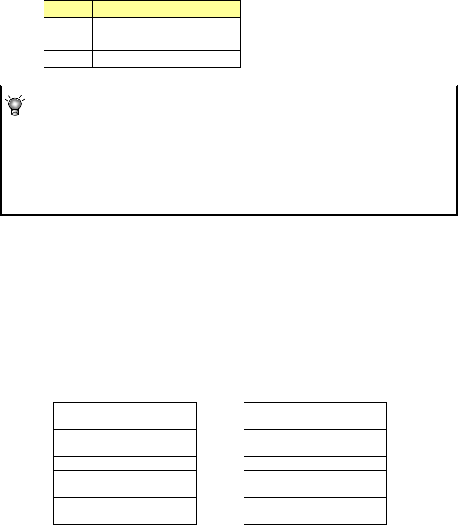
3) Specify group trays with same component type together
Regarding the same type tray components to be supplied to the MTC/MTS, specify whether
to arrange trays collectively or arrange them giving priority to the feed speed.
a) Group trays with same component type together:
Trays are arranged for each sane component type.
b) Arrange trays to optimize supply time:
Trays are arranged by giving priority to the feed speed.
Comp Type A
Comp Type A
A
Comp Type B
A
Comp Type C
Comp Type B
A
B
B
B
C
Comp Type C
A
C
B
C
C
When “Group trays with same
component type together” is
selected
Arrangement with supply
speed priority
Part 1 Basic Operation Chapter 4 Creating a Production Program
4-136
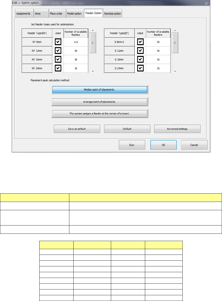
(5) Feeder Option
Set the calculating method for the feeder type to be used for optimization and feeder layout.
1) Feeder type setting
For an electric feeder that has two or more feeder types for the same tape width, set a
“feeder type used for optimization.” When you select two or more feeder types, the system
uses the optimal feeder among the selected feeder types to generate Pick data.
Item name Contents
Feeder Type (EF, RF) Shows the electric tape feeder type.
Used
Select whether the target feeder is used for optimization.
When checked on, the feeder is used for optimization.
Number of available feeders Set an upper limit to the number of target feeders used for optimization.
Feeder type Input range Feeder type Input range
RF 8 mm
1 - 112
E 8 mm S
1 - 56
RF 12 mm
1 - 56
E 12 mm
1 - 56
RF 16 mm
1 - 56
E 16 mm
1 - 36
RF 24 mm
1 - 36
E 24 mm
1 - 36
RF 32 mm
1 - 28
E 32 mm
1 - 28
RF 44 mm
1 - 22
E 44 mm
1 - 22
RF 56 mm
1 - 18
E 56 mm
1 - 18
RF 72 mm
1 - 12
-
-
RF 88 mm
1 - 10
-
-
If the number you set on the screen for setting the number of components exceeds the total
of the number set in the “Number of available feeders” for the electric tape feeder when you
press the <Run> button, the Optimization utility cannot be executed.