RS-1_instruction manual.pdf - 第31页
Part 1 B asic O peration Chapter 1 Overv iew of the Machine 1- 13 Part na m es of the ov erall excha nge feeder trolley f or t he electric tape fe eder Set the tape ree l in the re el holder ① . Raise the E - bank ② an…
Part 1 Basic Operation Chapter 1 Overview of the Machine
1-12
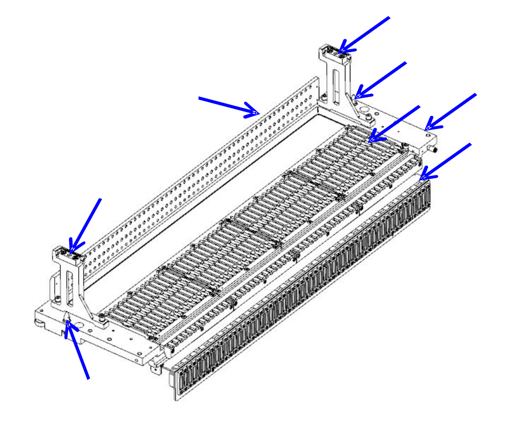
Part names of the bank for the electric tape feeder
Insert the electric tape feeder along the rail guide ① until it is in contact with the fixing block ②
and make the positioning.
Set the electric tape feeder on the bank, seeing the position label ③.
The bank mark ④ is intended to correct the position and posture of the bank.
①
Rail guide ③ Position label ⑤ Locate pin
②
Fixing block ④ Bank mark ⑥ Bank base
④
①
③
⑤
⑥
②
⑤
④
Part 1 Basic Operation Chapter 1 Overview of the Machine
1-13
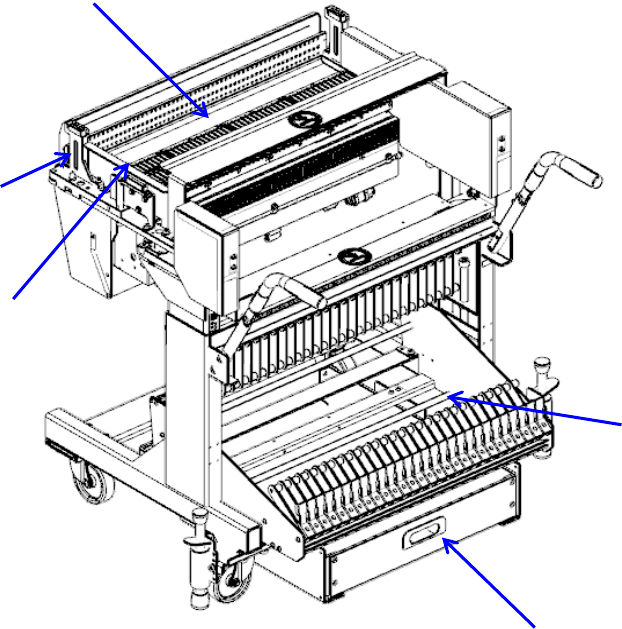
Part names of the overall exchange feeder trolley for the electric tape feeder
Set the tape reel in the reel holder ①.
Raise the E-bank ② and make the positioning with the locate pin ③.
When changing the tape at the setup position, connect the setup connector ④ to the connector on
the ETF side.
Tape reel exchange of RF series electric feeder is done on the set-up stand for electric feeder
(optional).
Carrier tapes, which have been cut during operation of the mounter, accumulate in the trash box ⑤.
①
Reel holder
③
Locate pin
⑤
Trash box
②
E-bank
④
Setup connector
⑤
②
④
③
①
Part 1 Basic Operation Chapter 1 Overview of the Machine
1-14
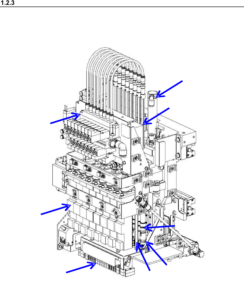
Configuration of the head unit
The head unit consists of the laser sensor used to detect placement and angle offsets of the
component, and the Z slide shaft which can be moved up and down, or be turned. The machine is
equipped with the head unit as shown below.
① Nozzle outer ④ Z slide shaft ⑦ Head up cylinder
② LNC120 sensor ⑤ θ-axis motor ⑧ Filter box
③ Z-axis motor ⑥ Ball screw
①
②
③
④
⑤
⑥
⑦
⑧