RS-1_instruction manual.pdf - 第262页
Part 1 B asic O peration Chapter 2 Pr oduction 2- 151 (3) R estart m ode Specify ho w to restart the suspende d PWB producti on. Menu item Description Retry Retries to p ick up and place a compone nt that caused an er ro…

Part 1 Basic Operation Chapter 2 Production
2-150
(1) Cause
This menu item shows the cause of an error or that the system pauses.
The possible causes are shown in the table below.
No.
Cause
1
Not select “Stop system on any error”
2
Step production mode
3
User request with the <STOP> switch
4
Cover was open
5
Feeder bank down
6
The sensor detects a floating feeder error
7
Air has not been supplied.
8
Mark recognition error
9
Empty component
10
Component protection
11
Retry list
12
The Operation options
13
Other production error has occurred
14
Tombstone
15
Laser recob. error
16
A board transportation error has occurred
17
The laser head is stained
18
The mark has not been taught
19
Tracking a component placement position when production is resumed
20
Pause with the <CYCLE> switch
21
Pause for resume operation
22
Copla Error
23
Flux Container is empty.
24
Sensor Unworking
25
An empty pocket overdetection
26
No empty pocket
27
Splicing Verify Error
28
Splice sensor unavailable
29 Lock lever OFF
30 Feeder bank moving down
31 IC collection belt full
(2) Production operation
The items of the current operations for the target bank are shown here.
Menu item
Description
Head name
Displays the head number.
Circuit No.
Displays the number of the circuit on which the head picks up and places a component.
Step No.
Displays the record number of the “Placement data” on a component that the head picks up and
places on a board.
Total Pl.
Displays the number of components that have been placed on a board.
Pick Pos.
Displays the position from which the head picks up a component.
Nozzle
Displays the number of a nozzle that is attached on the head.
Cmp name
Displays the name of a component that the head is picking up.
Place ID
Displays the Place ID that the head is picking up.
Part 1 Basic Operation Chapter 2 Production
2-151
(3) Restart mode
Specify how to restart the suspended PWB production.
Menu item
Description
Retry
Retries to pick up and place a component that caused an error.
A feeder that is located on the station that displayed the “Stop” screen and whose components have
run out is automatically refilled with components.
Skip
Skips placement of a component that caused an error.
(4) Execution mode
Select whether to produce PWBs continuously or stop production at each step.
Menu item Description
Continuous The system continues producing PWBs until it finishes the production or the production is aborted.
Step
The system pauses at each movement operation.
Your pressing the <START> switch restarts the suspended production.
(5) Action
These buttons allow you to move the axis.
Menu item Description
Head Wait
Moves the head to the waiting position.
Laser wave
Displays the laser waveform screen and allows you to check the laser
See Section 2.15.8 Component protection.
Image data Save file
Outputs the VRAM image as a file.
Machine data Save file
Outputs machine information, error history and image information as a file.
Cover Lock Release
Unlocks the protection cover when any component is not picked up with a head.
(6) Edit Data
These buttons allow you to change data on the Retry list.
Menu item Description
Error Detail
Displays the “Error Detail” screen for the pause condition.
Supply
Refills a feeder on which components run out with components.
Get image data
Obtains information on a VCS, and then displays the detailed information on a VCS error.
See Section 2.11.4.2 Displayed screen (2) Retry list (not placed) 3) Error (Detail – Mark
Recog./VCS Recog.).
Part 1 Basic Operation Chapter 2 Production
2-152
Tracking
If you press the “Trace” button displayed in the Operation area when the “Stop” screen is displayed,
the system enters Tracking mode of a component pick-up position.
You can track a component pick-up position of all feeders that supply components that caused a
retry error or a component run-out error.
However, the system does not track a component pick-up position of a feeder that is set to
“Unused.”
See Section 2.14.7 “Tracking a component pick-up position with a camera” for details.
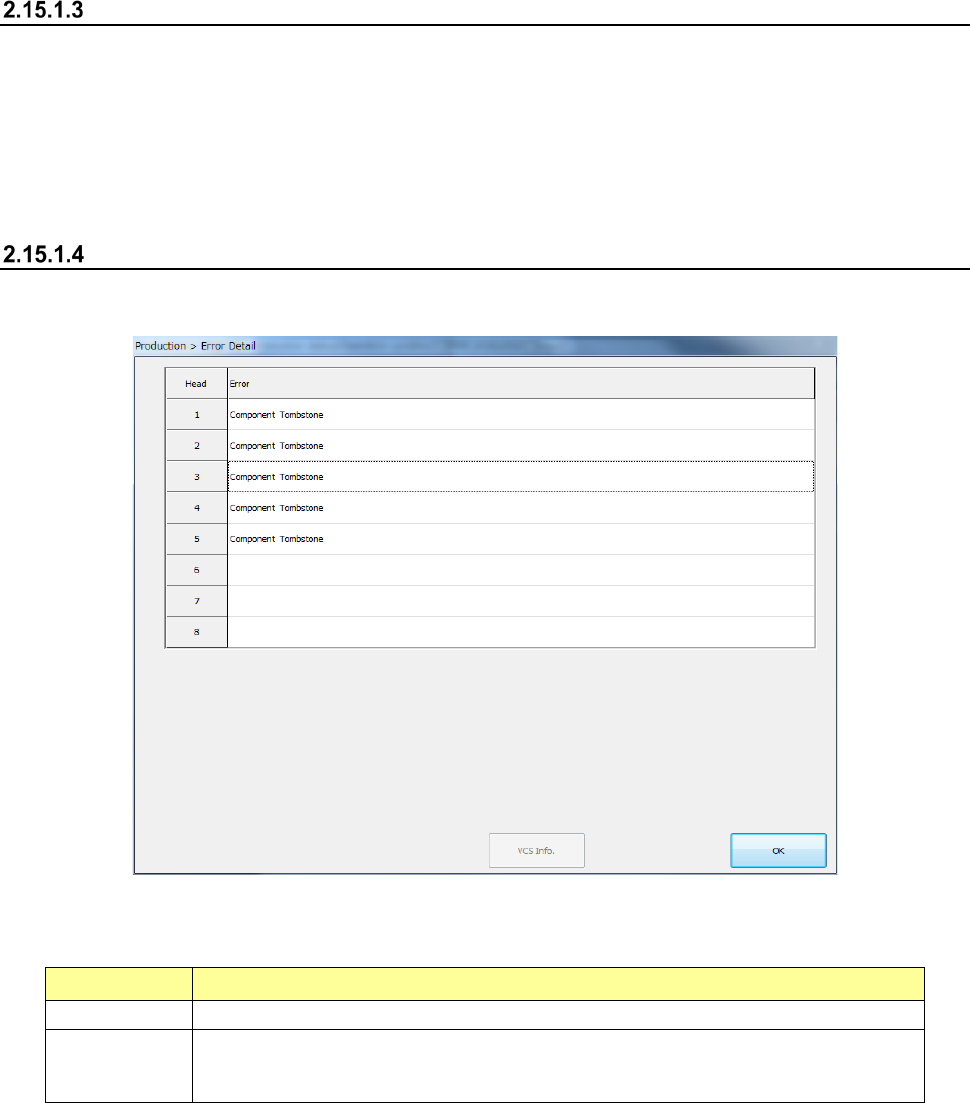
Error Detail
When you press the <Error Detail> button on the “Pause” screen, the “Pause (Detail)” screen
appears.
(1) List of the error heads
A list of heads at which an error occurred is displayed.
Menu item Description
Head
Displays the number of each head.
Error
The displayed data is the same as that displayed in the “Error” column of the “Retry list.”
See “2) Error (Type) of Section 2.11.4.2 “Displayed screen” for details.
See “Error (Detail)” of Section 2.11.4.2 “Displayed screen” for details.
When you press the <OK> button, the system quits the “Pause (Detail)” screen, and then
displays the “Pause” screen again.