RS-1_instruction manual.pdf - 第609页
Part 1 B asic O peration Chapter 4 Cr eating a Produc tion Progra m 4- 274 Element t ype Explanation Lead Element gr oup data consisti ng of leads is created. Side Element group data consi sting of sides i s created. Cor…
Part 1 Basic Operation Chapter 4 Creating a Production Program
4-273
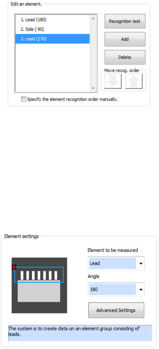
⑦ Element editing (general-purpose vision component (lead/outline))
Addition, deletion, and recognition order for multiple element groups are performed. In
addition, a recognition test can also be made.
In the initial status of element editing, the element setting screen appears automatically.
a) To add a new element group, press the <Add> button.
Set the type and angle of the element to be added and then add the element group. When
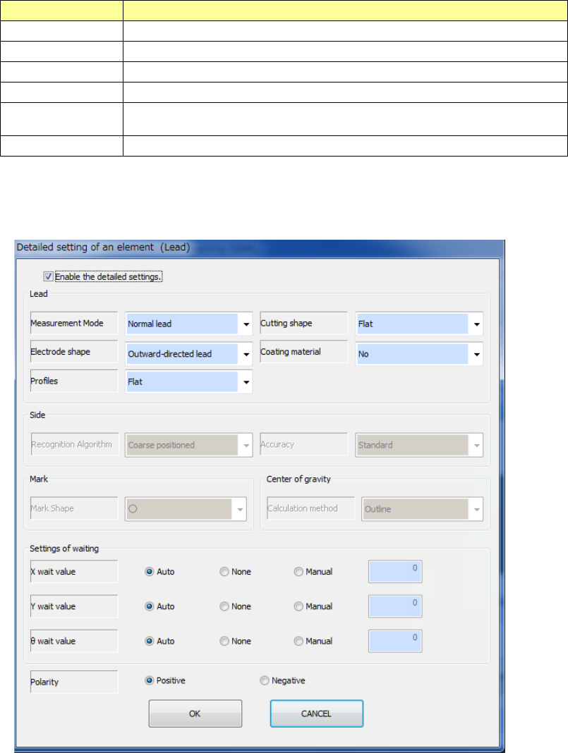
you press the detailed setting button, a detailed setting dialog is displayed to perform
settings more finely.
b) To delete an existing element group, select the element group to be deleted and press the
<Delete> button.
c) To test whether an element can be recognized according to the settings of the current
element group, press the <Recognition test> button.
d) To change the element group recognition order, check off "Specify the element recognition
order manually."
e) To change the recognition order, select the element group to be changed and press the
Up/Down button of "Recognition order shift." The element group position is shifted up and
down.
f) After completing editing all the element groups, press the <End Teaching> button.
Part 1 Basic Operation Chapter 4 Creating a Production Program
4-274
Element type Explanation
Lead Element group data consisting of leads is created.
Side Element group data consisting of sides is created.
Corner Element group data consisting of corners is created.
Mark Element group data consisting of marks is created.
Center of gravity Element group data consisting of center of gravity for rough positioning is
created.
User definition Element groups consisting of image data for direction inspection are created.
- When the element type is “Lead,” “Side,” “Corner,” “Mark” or “Center of gravity”
See Chapter 6 “General-Purpose Vision Component” for details of the settings.
Part 1 Basic Operation Chapter 4 Creating a Production Program
4-275
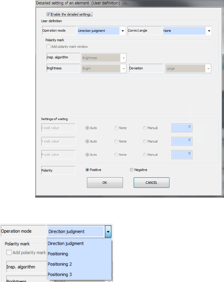
- When the element type is “User definition”
● Operation mode
Specify the operation mode of the user-defined element.
- Direction judgment
Creates the definition for direction judgment only.
You have to create a side element and/or a lead
element for positioning also.
- Positioning
Creates the definition for positioning only: this is for
centering.
You cannot create a side element or a lead element.
- Positioning 2
Creates the definition for positioning and that for direction judgment (one group).
The system determines the direction with the brightness on the window set for editing a
component. Therefore, the system does not memorize the shape. To determine the
direction with the shape, select “Positioning 3.”
- Positioning 3
Creates the definition for positioning and that for direction judgment (one group).
The system determines the direction with the shape set on the window for editing a
component.
You cannot create a side element or a lead element if you select this setting.
When you select “Positioning,” “Positioning 2” or “Positioning 3” as the “Operation mode,”
you can set up to eight windows for areas to be used for recognition. While you are editing a
user-defined element for positioning, the displayed screen for editing an element is changed.
After selecting an area, select the <Add> button to continue to edit an element or the
<Editing complete> button to finish editing an element.