RS-1_instruction manual.pdf - 第408页
Part 1 B asic O peration Chapter 4 Cr eating a Produc tion Progra m 4- 73 3) Pla ce Offset X, Y , Ө When the syst em cent ers a component with laser , it holds the center of the component based on t he outlin e of the co…
Part 1 Basic Operation Chapter 4 Creating a Production Program
4-72
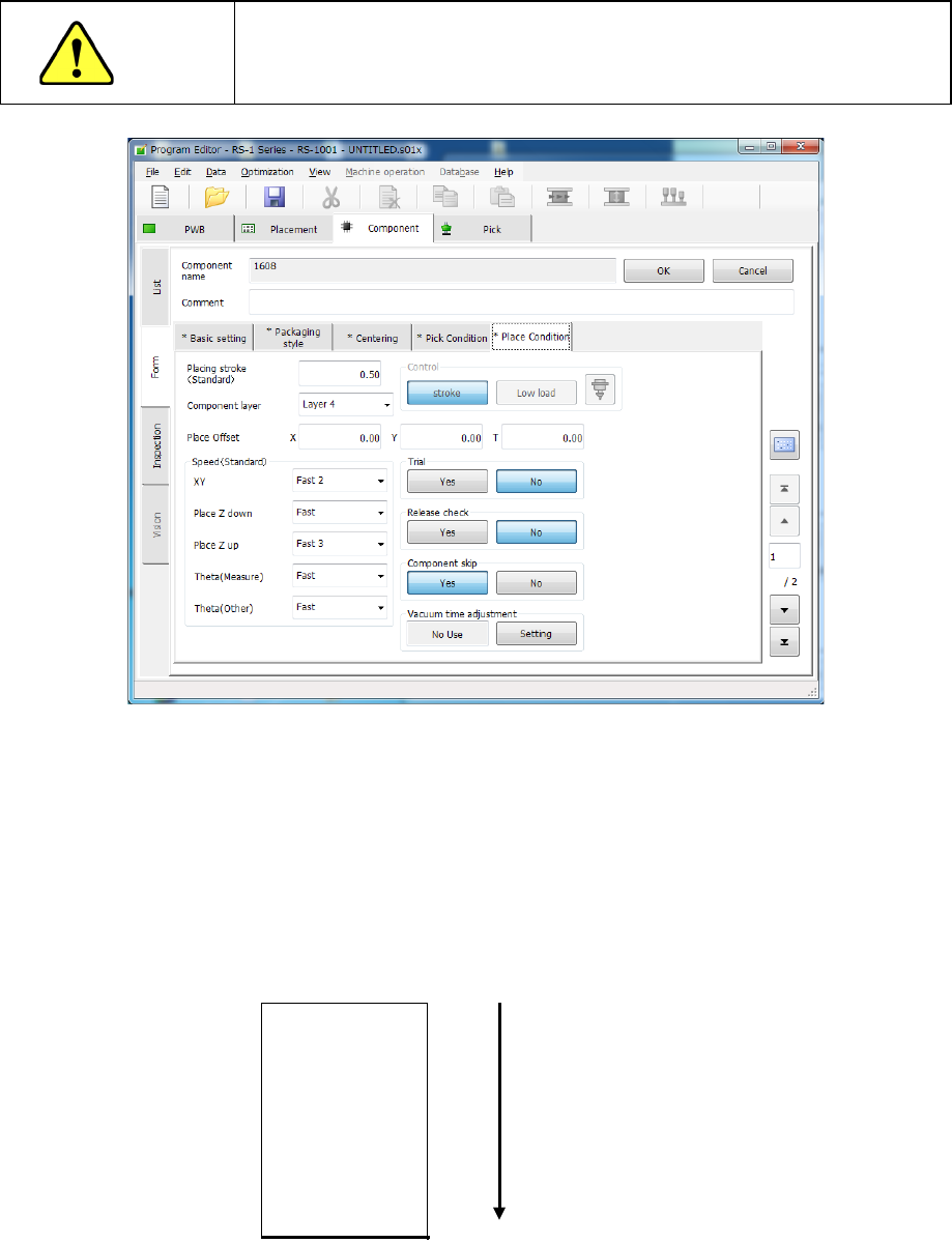
(5) Place Condition
The placement conditions consist of setting items related to placement and default values
are applied. Accordingly, they do not need to be changed. If placement cannot be
performed normally in the default value status, change the settings. Note that if you change
the setting(s) of the “Basic setting” tab sheet after changing the settings of the “Place
Condition” tab sheet, settings of some menu items are reset to the default ones.
CAUTION
If you change any of the basic settings after changing any value on the
“Place Condition” tab, some values are reset to their defaults on the
“Place Condition” tab.
1) Placing stroke
Specify how much to push the tip of a nozzle when a component is placed on a board.
2) Component layer
The “Component layer” field specifies the priority of each component on the same
placement layer.
This selection is effective only if the system produces a PWB in the optimized order.
Note that since this setting is for the priority of the optimized placement order, this does not
specify the placement order strictly, so that this does not put the machine into the pause
state when components run out unlike the placement layer.
Select the layers from 1 (highest priority) to 7 (lowest priority) from the pull-down list.
Layer 1
Layer 2
Layer 3
Layer 4
Layer 5
Layer 6
Layer 7
Place first.
Place later.
Part 1 Basic Operation Chapter 4 Creating a Production Program
4-73
3) Place Offset X, Y, Ө
When the system centers a component with laser, it holds the center of the component
based on the outline of the component observed with laser.
In CAD data or similar type of data, the center of the component-mounted pattern (called
“pad”) is regarded as the coordinates of the component placement position.
This difference may cause leads of a component to be shifted from the pad of a PWB.
Therefore, when you enter this difference in this “Place Offset,” the system can place a
component at the correct position.
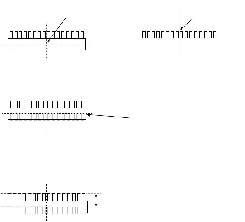
Example 1: One-direction lead connector
* Placement angle is 0°.
If the placement offset is not entered, components will be placed as shown below.
In the condition shown in the figure above (placement angle of 0º and placement offset of 0),
the system measures the distance from the coordinates of the component placement
position as the start point to the relative position of the component placement position
coordinates, and enters this distance into the “Place Offset” field.
To place two or more components of the same name, enter the placement offset in this
manner, and the placement position will be automatically changed and the component will
be placed on the correct position even if each placement angle is other than 0°.
Placement offset -Y (X is 0)
Center position of a component
centered with laser
Placement coordinate
position
Top view of a component
Pad on a PWB
Pad on a PWB
Part 1 Basic Operation Chapter 4 Creating a Production Program
4-74
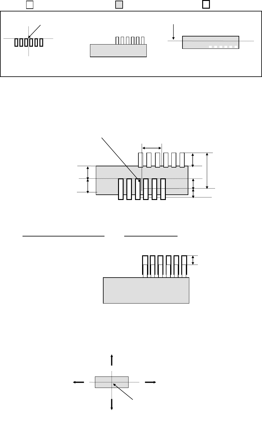
Example 2: Taking the following component as an example, enter the offset value. The unit of
numerical value is "mm (millimeter)."
( (no color) ⇒ Lead section, (colored) ⇒ Mold section, (bold line) ⇒ Pad)
Since the coordinates of the component placement position are different from the center
position of the component centered with laser, the system will not place a component at the
correct position. Therefore, enter this difference into the “Place Offset” field as the offset
value.
If any offset is not entered, components will be placed as shown below.
In this case, enter an offset value so that the tip of the lead will come on the center of the
pad.
If "X = -5.5, Y = -10" is entered in the "Place Offset" field, components will be placed as
shown below.
Note 1: Enter the length from the center position of a component centered with laser to the
coordinates of the component placement position in the “Place Offset” field. For the
sign of the value, see the figure below (the arrow mark means the length to the
coordinates of the component placement position).
Coordinates of the component placement position
Laser height
Pad on a PWB
Top view of a component
Lateral view of a component
(from the front)
2
Center position of a component
centered with laser
−Y
+Y
+X
−X
Center position of a component centered with laser
3
5.5
10
2
2
5
5