RS-1_instruction manual.pdf - 第894页
Part 2 D etaile d Descript ion of E ach Functi on Chapter 12 Handling th e Optional Device s 12 - 10 * Notes on attac hment of an ETF onto the tape reel stand (1) Tw o 8 - mm to 24 - mm type ETFs ca n be attach ed on the…
Part 2 Detailed Description of Each Function Chapter 12 Handling the Optional Devices
12-9
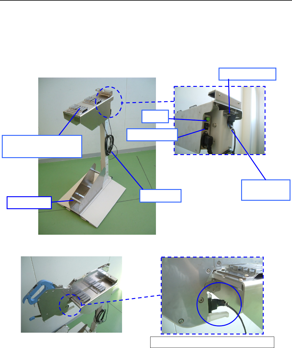
12.1.2.2 Procedure for setting a tape with the set-up stand EF for an EF series electric feeder.
(1) Connect the power plug of the tape reel stand to the AC outlet to supply power to the stand.
(2) Set the power switch to ON. Check to see if the lamp lights.
(3) Attach the ETF onto the ETF work base.
(4) Disconnect the connector for offline setup from the ETF power hook, and then connect it to
the connector of the ET F.
(5) Place the tape reel on the reel holder, and then set a tape onto the ETF.
(Refer to the “ETF Instruction Manual” for how to set a tape onto the ETF.)
Enlarged view of the rear of the
ETF attachment section
Overall view of the tape reel stand for an ETF
Enlarged view of connector connection
Connector for
off-line setup
ETF power hook
Lamp
Power plug
Reel holder
ETF work base
(ETF attachment section)
Power switch
Part 2 Detailed Description of Each Function Chapter 12 Handling the Optional Devices
12-10
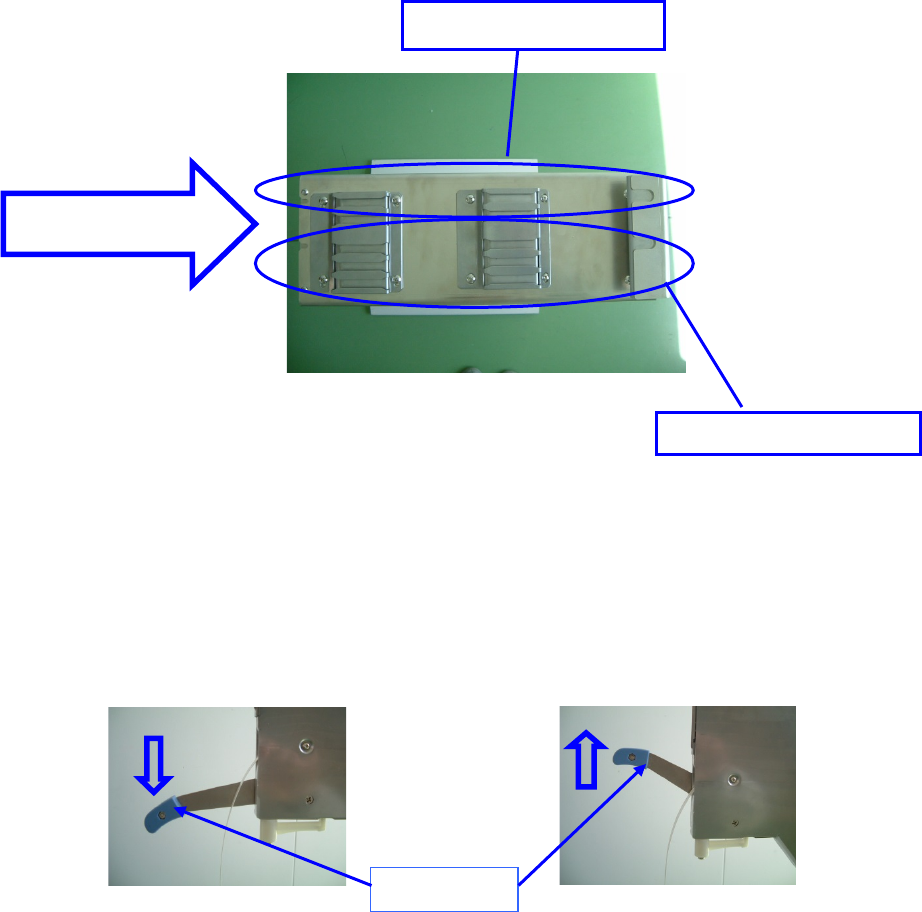
* Notes on attachment of an ETF onto the tape reel stand
(1) Two 8-mm to 24-mm type ETFs can be attached on the stand.
One 32-mm to 56-mm type ETF can be attached on the stand.
The following figure shows where to attach an ETF.
Top view of the tape reel stand for an ETF
(2) Checking to see if a clamp lever is locked
Make sure that the clamp lever is raised (when the lever is locked) to attach the ETF onto the
tape reel stand.
Make sure that the clamp lever is lowered (when the lever is unlocked) to detach the ETF
from the tape reel stand.
When the lever is released When the lever is locked
ETF attachment
direction
ETF 8mm to ETF 56mm
ETF 8mm to ETF 24mm
Clamp lever
Part 2 Detailed Description of Each Function Chapter 12 Handling the Optional Devices
12-11
12.2 Electric bank multi-tray holder
This tray holder is equipped with one tray, and can be installed on the rear bank so that the head of
the main unit can pick up a component directly from this holder.
When the tray size is small, several trays can be attached on the holder to allow this holder to
function as a multi-tray holder.
Full type
Half type
Longitudinal direction 65 mm to 320 mm 65 mm to 155 mm
Horizontal direction 65 mm to 259.5 mm 65 mm to 259.5 mm
Thickness
5 mm to 11 mm
(from the bottom of a tray to the top of an IC)
Number of occupied positions
28
14
* A number of available places at the rear side. Full type: 2 tray holders, - Half type: 4 tray
holders
* If the thickness is not shown above, contact our sales person in charge.
Do not replace the tape feeder with another one while the X- or Y-axis, or head
is operating. It may cause a serious injury to the operator or damage the
machine itself since the tape feeder touches the operating parts.
Do not dismount the tape feeder while the X- or Y-axis or head is operating.
Be sure to open the safety cover before replacing a feeder with another one.
After setting feeders required for PWB production at the positions specified with
a production program respectively, set feeders not to be used for production
such as an 8-mm tape feeder at all the positions not occupied with the feeders
above so that any finger or hand cannot be put between the set feeders to
secure your safety.
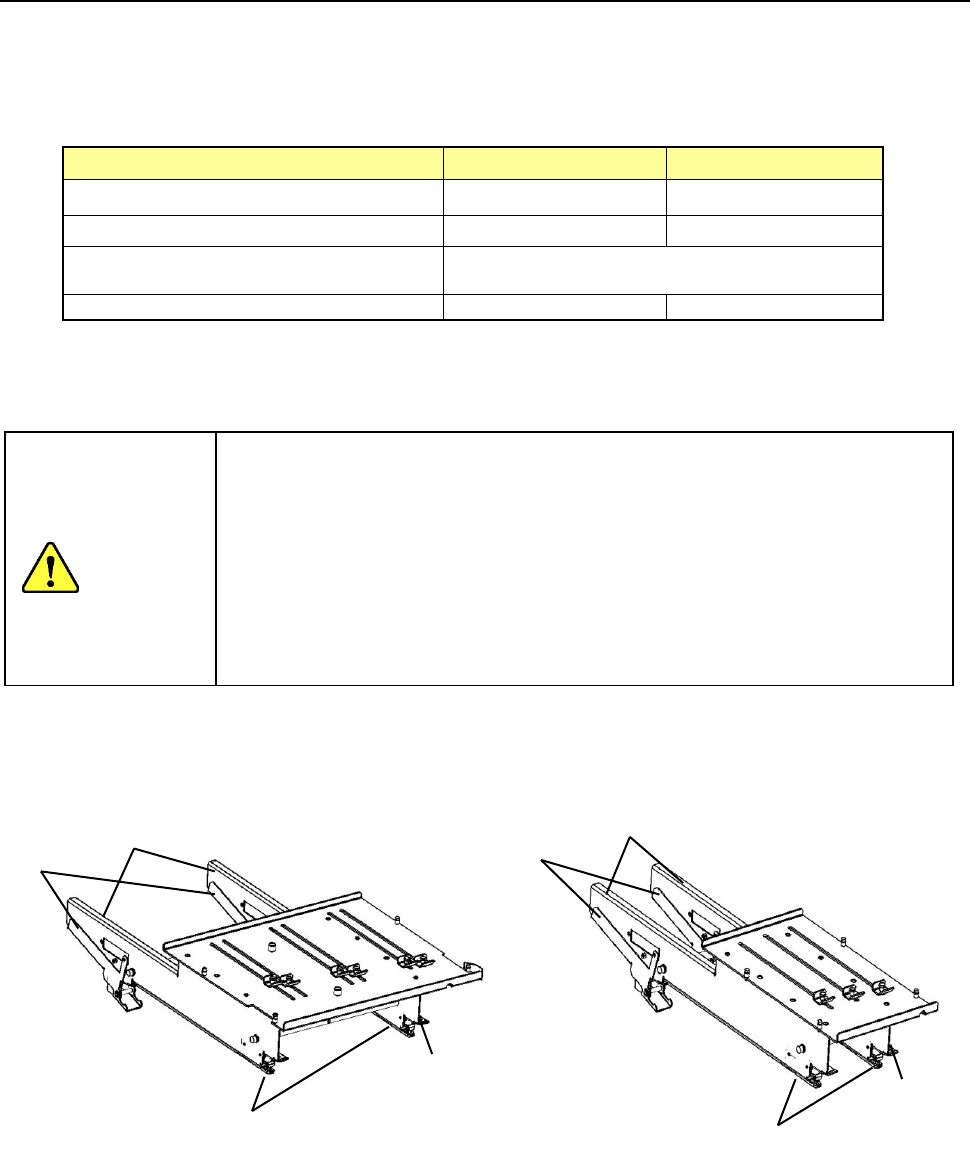
- Full size - Half size
① Side plate
② Tray lock lever
③ Slide rail
④ Guide pin
①
②
③
④
①
②
③
④
CAUTION