RS-1_instruction manual.pdf - 第392页
Part 1 B asic O peration Chapter 4 Cr eating a Produc tion Progra m 4- 57 ④ T ray thickness Enter the tr ay thicknes s from the t ray bottom to the top surf ace including comp onents. When the th icknes s “T” of a tray o…
Part 1 Basic Operation Chapter 4 Creating a Production Program
4-56
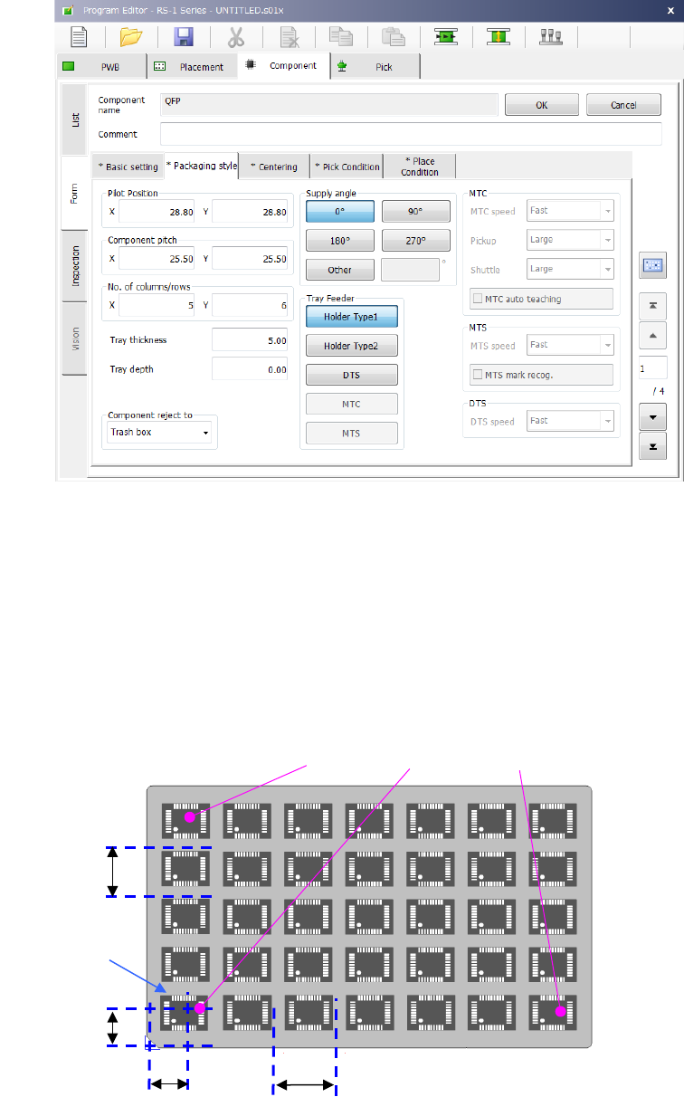
3) Tray input method
① Pilot Position
Enter the distance from the tray outside to the center position (X, Y) of the first tray
component.
② Pitch between components
Enter the pitch between components (Pitch X, Pitch Y).
③ No. of columns/rows
Enter the number of components (Xn, Yn) in the lateral direction and the longitudinal
direction.
After the pickup data supply position is determined, the coordinates of 3 positions of the tray
are displayed in the pickup data. (X
1
, Y
1
to X
3
, Y
3
)
First component position X
First component
position Y
First
component
Pitch X
Pitch Y
(
X
2
,Y
2
)
(
X
1
Y
1
)
(
X
3
Y
3
)
Part 1 Basic Operation Chapter 4 Creating a Production Program
4-57
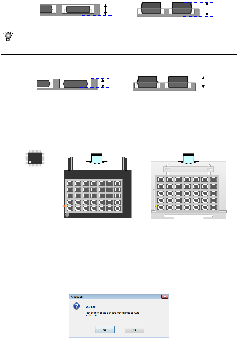
④ Tray thickness
Enter the tray thickness from the tray bottom to the top surface including components.
When the thickness “T” of a tray of an MTC/MTS exceeds 9 mm, any tray base cannot be set
on the stage immediately above the stage on which this tray is set. When the thickness “T” of
a tray exceeds 23 mm, any tray base cannot be set on the stage two levels higher than the
stage on which this tray is set either. The maximum thickness “T” of a tray is 36 mm.
⑤ Tray depth
Enter the depth of the tray.
⑥ Supply angle
Enter an angle at which the component packing style on the stick feeder is inclined to the
JUKI component supply angle of 0°
For details, refer to "4.3.5.2(2) Packaging style 1) How to enter data when you select “Tape”
the “Packaging style”, * JUKI component feed angle definition."
When you select “Other,” enter the angle in the edit field. (0º to 359.9875º)
⑦ Component reject to
Set the component discarding method for a case where centering results in a recognition
error or lead floating inspection results in an error. For details, refer to "4.3.5.2(2) Packaging
style 1). How to enter data when you select “Tape” the “Packaging style”, Component
discarding."
⑧ Tray Feeder
Select a tray feeder among “Holder,” “DTS,” “MTC” and “MTS.”
If you change the setting of a tray feeder of a component for which two or more records of
pick data have been entered, the following message appears on the screen.
Angle definition 0°
供給角度 180°
供給角度 0°
Supply angle 0°
Supply angle 180°
Supply from the rear bank
Supply to the MTC, or MTS
Tray depth
Tray depth
Tray
thickness “T”
Tray
thickness “T”

Part 1 Basic Operation Chapter 4 Creating a Production Program
4-58
⑨ MTC
- MTC speed : You can specify the operation speed of the shuttle.
When you decrease this speed, the MTC can supply the main unit with
components more stably, but the cycle time becomes longer.
- Pickup : You can specify the type (Large or Small) of the pad on the MTC pick-up
side.
* When you select “Auto,” the system selects both pads for the same type
components during production as long as the size of these components is
in the range of □10 mm to □14 mm (□10 mm to □16 mm when a
seesaw nozzle is used), and then picks up these components.
- Shuttle : You can specify the type (Large, Small or Mecha) of the pad on the MTC
shuttle side.
* Since a ball component such as a BGA component cannot be picked up
with the pad of the MTC shuttle (that is, vacuum cannot be used),
specify “Mecha” (for clamping the outside of a component).
* When “Tray return” is specified for the menu item “Component reject to”
on the “Add info” tab, the choice “Mecha” cannot be selected.
◆ Initial values for the MTC pads
Menu item displayed on
the screen
Default value
Pickup
–
When the length of the shorter side, width or length, of
the component dimensions is
Less than 16 mm : Small
16 mm or more : Large
Shuttle
–
When the component type is BGA: Mecha
– When the component type is not BGA and the length
of the shorter side, width or length, of the component
dimensions is
Less than 16 mm : Small
16 mm or more : Large
- MTC auto teaching : When you check off this check box, the system automatically
calculates the center of a component at each point to show you
the center of the component with the spot light. During
production, auto teaching is performed when a component is
pulled out for the first time after the number of components is
changed once auto teaching is performed.
⑩ MTS
• MTS speed
Specify the tray pull-out speed. This prevents lightweight components from jumping.
• MTS mark recognition
Then the MTC is used, and the pick reference position mark recognition is set to "Do,"
the pick reference position mark is recognized when the tray where the set components
are placed is pulled out, and the execution coordinates such as the pick and the
component return is corrected.
It takes the recognition time though the pick accuracy improves when "Do" is selected.
⑪ DTS
- DTS speed: Specify the speed at which a tray is pulled out. This setting is provided to
prevent a lightweight component from bouncing.