RS-1_instruction manual.pdf - 第260页
Part 1 B asic O peration Chapter 2 Pr oduction 2- 149 2.15 Error Handli ng and Pause durin g PWB Productio n This section de scribes how to han dl e an err or that occurs during PW B product ion and the process to be per…
Part 1 Basic Operation Chapter 2 Production
2-148
position. You can enter a component placement position as a value directly also. When
you enter a component pick-up position and press the <ENTER> key, the head starts
moving.
• When you press the <NEXT> button or the <PREV> button in the “Progress” column, you
can change a component pick-up position to be taught.
When you press the <START> switch, the system resumes automatic tracking of a
component pick-up position with a camera.
When you press the <START> switch at the last component pick-up position, the system
displays the confirmation message for starting production.
When you press the <STOP> switch, the system displays the dialog box for asking you
whether to abort tracking operation, and then aborts tracking of a component pick-up
position with a camera. Since the system replaces nozzles even though you press the
<STOP> switch, the XY-axes, nozzles and heads continue moving.
CAUTION
- Check to see if there is no one who is operating the insides of the machine.
- Check to see if there is no one who is near the machine and may be injured.
- Check to see if there is no adjustment tool that may prevent each operation of the insides
of the machine is attached or placed to/in the machine.
- To prevent any accident causing injuries, never put your hand in the machine or never
bring your face or head close to the machine while it is operating.
Manual
When you select “Manual” as the menu item “Pick tracking,” the camera moves to the first
component pick-up position after a component is picked up.
Then, the system displays the monitored image on the screen, and pauses temporarily.
Automatic teaching the component pick-up position
This automatic component pick-up position teaching function allows you to teach the component
pick-up position automatically when necessary.
To use this function, you have to enable the corresponding operation option (check the “Auto-teach
at pick position” option).
Note that only the pick-up position of a component whose “auto-teaching” menu item is enabled on
the “Component data” screen can be automatically taught.
When you track a component pick-up position on a component supply unit where components run
out at start or restart of PWB production, the system automatically teaches the component pick-up
position.
WARNING
When you check the “Yes” radio button of “Auto teaching,” the head moves.
• To avoid injuries, do not put your hands inside the machine or keep your face or head
away from the machine.
• If the machine does not recognize a feeder bank yet, the head moves across the feeder
when you perform a teaching operation (immediately after the axes return to their home
positions or immediately after the bank moves up). Do not put your hands inside the
machine or keep your face or head away from the machine.
• When you use the HMS, be careful to prevent any laser beam from entering your eye
directly or with reflected from a mirrored surface.
Part 1 Basic Operation Chapter 2 Production
2-149
2.15 Error Handling and Pause during PWB Production
This section describes how to handle an error that occurs during PWB production and the process
to be performed when the system pauses.
If an error occurs
When you check the option “Stop system on any error” on the “Operation option” screen, the system
stops the current PWB production temporarily if any targeted error occurs, and then displays the
“Pause” screen.
At this time, an error displayed on the “Retry list” causes the system to pause.
This section describes types of errors that may occur and the conditions under which the system
pauses.
Overview of errors and pause
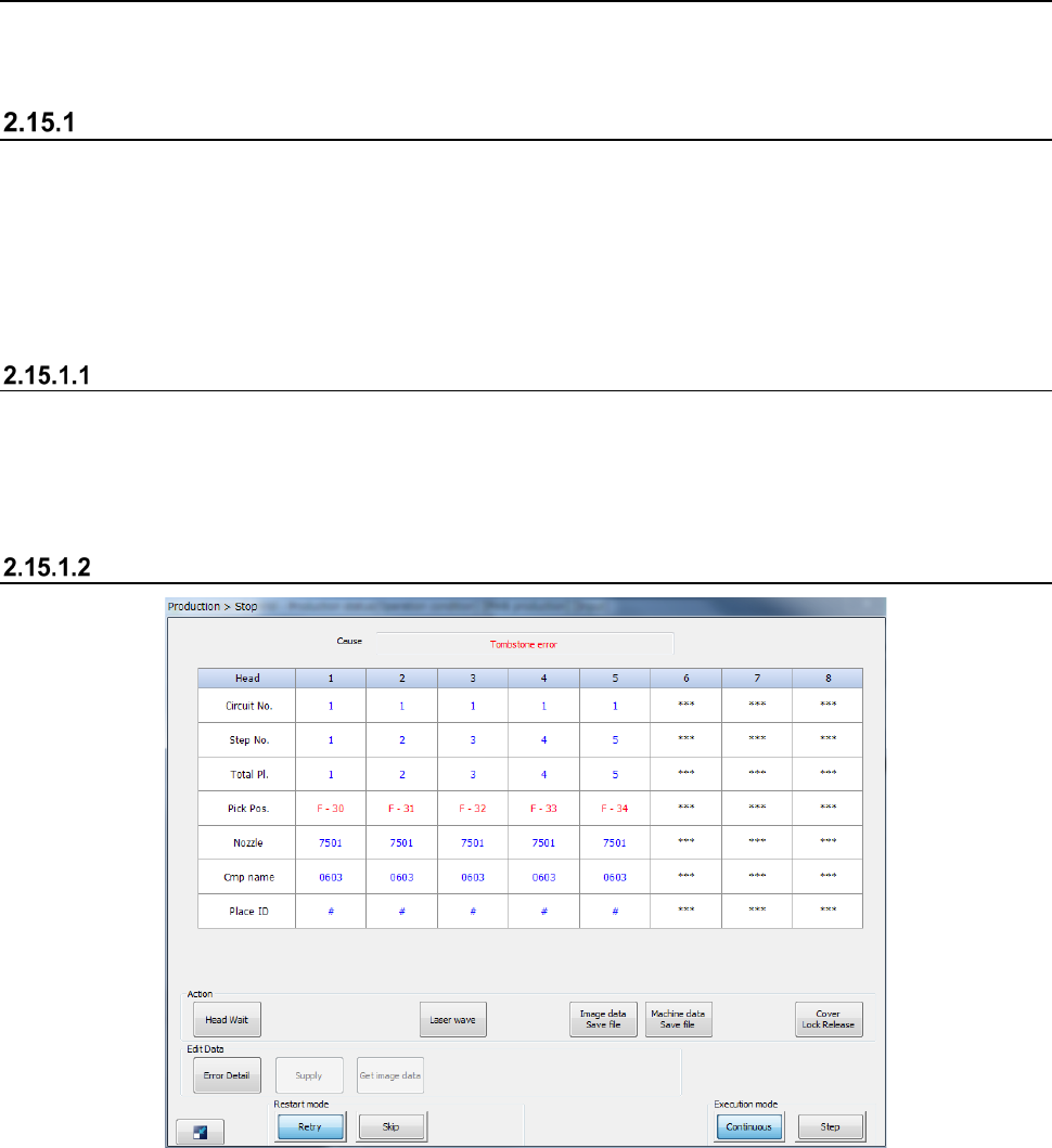
The following screen appears if an error occurs or the system pauses.
- When you press the <START> switch, the system restarts PWB production.
- When you press the <STOP> switch, the system displays the “Question” dialog box to start
aborting the production.
Displayed screen

Part 1 Basic Operation Chapter 2 Production
2-150
(1) Cause
This menu item shows the cause of an error or that the system pauses.
The possible causes are shown in the table below.
No.
Cause
1
Not select “Stop system on any error”
2
Step production mode
3
User request with the <STOP> switch
4
Cover was open
5
Feeder bank down
6
The sensor detects a floating feeder error
7
Air has not been supplied.
8
Mark recognition error
9
Empty component
10
Component protection
11
Retry list
12
The Operation options
13
Other production error has occurred
14
Tombstone
15
Laser recob. error
16
A board transportation error has occurred
17
The laser head is stained
18
The mark has not been taught
19
Tracking a component placement position when production is resumed
20
Pause with the <CYCLE> switch
21
Pause for resume operation
22
Copla Error
23
Flux Container is empty.
24
Sensor Unworking
25
An empty pocket overdetection
26
No empty pocket
27
Splicing Verify Error
28
Splice sensor unavailable
29 Lock lever OFF
30 Feeder bank moving down
31 IC collection belt full
(2) Production operation
The items of the current operations for the target bank are shown here.
Menu item
Description
Head name
Displays the head number.
Circuit No.
Displays the number of the circuit on which the head picks up and places a component.
Step No.
Displays the record number of the “Placement data” on a component that the head picks up and
places on a board.
Total Pl.
Displays the number of components that have been placed on a board.
Pick Pos.
Displays the position from which the head picks up a component.
Nozzle
Displays the number of a nozzle that is attached on the head.
Cmp name
Displays the name of a component that the head is picking up.
Place ID
Displays the Place ID that the head is picking up.