RS-1_instruction manual.pdf - 第373页
Part 1 B asic O peration Chapter 4 Cr eating a Produc tion Progra m 4- 38 When you se lect the [Ed it] command or t he [Brow se] com mand on the po p - up menu invoked from the “List” sc reen or wh en you select the “ Ar…

Part 1 Basic Operation Chapter 4 Creating a Production Program
4-37
(4) Angle
Enter the component placement angle with regarding the “Supply angle” specified on the
“Component” data screen as the reference angle.
See the description of “JUKI’s definition of the component supply angle” under Section 4.3.5.2 (2)
“Packaging style” for the component supply angle.
(5) Component name
Enter the name of a component (up to 60 characters).
Each time a component name is entered, component data is created.
If the use of database is set when a component name is entered, the database is searched.
Then, if the same component name is detected, the component data is fetched into the program.
Upper-case characters and lower-case characters are handled as the same data but are indicated
with distinction on the display unit.
If the component name is registered in the database in advance, it is replaced with a component
name of the registered characters in the database.
(If the component name is a new one, it is displayed as it is entered. If the component name
already exists, this existing component name is displayed.)
(6) Head
Specify a head to be used for placing a component on a board.
You can select from a pop-up menu a head that is to be used to place a component when a PWB
is produced in Input order.
Auto
A head to be used is selected automatically.
Head1
The head 1 is specified.
Head2
The head 2 is specified.
Head3
The head 3 is specified.
Head4
The head 4 is specified.
Head5
The head 5 is specified.
Head6
The head 6 is specified.
Head7
The head 7 is specified.
Head8
The head 8 is specified.
“AUTO” is selected as the initial setting. When you execute the “Optimization” utility after
creating a production program, the system automatically selects the optimal head.
(7) Mark (Mark ID)
Select whether to correct a component placement position with an area mark when the system
places a component on a board from the pop-up list box.
When you enter the Placement ID, “No” (a mark is not to be used) is set in the “Mark” field by
default.
“No” or a mark ID (up to eight half-sized characters) is displayed in the “Mark” field on the screen.
To change the setting, touch the input field to open the pop-up menu, and then select the desired
command.
No.
Specify that any marks are not to be used.
Edit
Opens the “Area Mark” screen.
Browse
Opens the “Area Mark” screen. (You cannot edit any data on this screen.)
If you open the pop-up menu when two or more lines are selected, the [Edit] command is not
displayed on the pop-up menu.
Otherwise, three choices shown above are displayed.
When you select the [Edit] command, the “Area Mark” screen appears in Edit mode.
When you select the [Browse] command, you cannot edit any data on the “Area Mark” screen.
Part 1 Basic Operation Chapter 4 Creating a Production Program
4-38
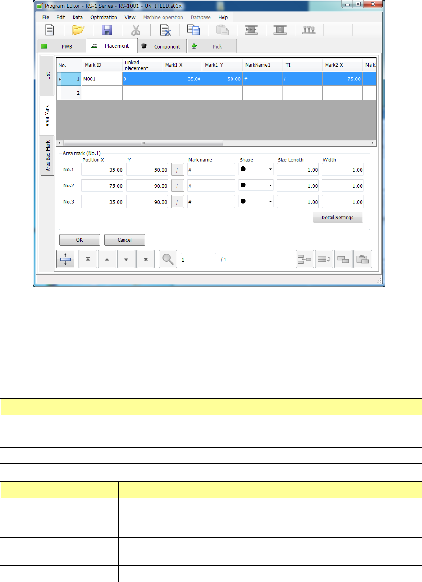
When you select the [Edit] command or the [Browse] command on the pop-up menu invoked from
the “List” screen or when you select the “Area Mark” tab, the “Area Mark” editing screen appears.
In the mark group list, a table of registered groups is displayed.
Select a group to be used in this table.
To register a mark, move the focus to a line in which no data is entered yet and enter the
X-coordinate and Y-coordinate of the mark.
After that, perform mark teaching or perform copying from the mark data to obtain the mark data.
The “Area mark” editing screen can be opened by the following method.
The processing varies depending on each display mode.
Operation Screen mode
[Edit] is selected on the mark pop-up menu. Edit/selection mode
[Browse] is selected on the mark pop-up menu Selection mode
The “Area Mark” tab is touched. Edit mode
Screen mode Contents of Processing
Selection mode
The mark data to be used by the placement data is registered. The
cursor on the list is displayed in a line selection status. The <OK> button
is indicated in light color.
Edit mode The coordinates of the mark can be entered and the mark teaching data
can be registered. The <Select> button is not displayed.
Edit/selection mode Selection and editing can be performed simultaneously.
Part 1 Basic Operation Chapter 4 Creating a Production Program
4-39
• Mark ID: Enter the Mark ID.
When you omit it, the system automatically assigns a mark ID.
• Linked placement: The number of placement data records that refer to a mark group when you
open the “Area Mark” screen is displayed here. You cannot edit any data.
• Mark 1(2, 3) X: Enter the X coordinate of a mark. The coordinate value can be obtained
with teaching operation.
• Mark 1 (2, 3) Y: Enter the Y coordinate of a mark. The coordinate value can be obtained
with teaching operation.
• Mark Name: The name of the mark is entered. The mark name can be taught or copied
from the mark data.
• Mark 1(2, 3) TI: The mark taught data obtaining status is displayed here. When the focus
is located here, you can teach the mark or copy it from the mark data.
The above items cannot be edited when the screen is opened by the [Browse] command. When
the screen is opened by the[Browse] command, they are displayed in the line selection mode.
• Select: The system selects a mark group on which the focus is located on the list
(that is, sets it into Placement data), and returns to the “List” screen of the
Placement data.
• OK: The system stores the edited data, and returns to the “List” screen of the
Placement data. Any mark group is not selected.
• Cancel: The system discards your editing, and returns to the “List” screen of the
Placement data.
When you quit the “Area Mark” screen with touching the “List” tab of the “Placement” data screen,
the system returns to the “List” screen without setting any link to the Placement data.
Since an area mark is affixed nearer a component placement position than a BOC
mark, it improves the accuracy of component placement. However, it takes a long
time to recognize a mark, so production is delayed.
CAUTION
If there is any CAD data (designed value) on a mark, NEVER teach the X
and Y coordinates. Should you do this, a component placement position
will be deviated.
The placement coordinates of the component that uses area marks have no
relation with the BOC marks. The BOC mark in this case works as the
reference coordinates for searching area marks. Therefore, if a component
is not placed on the specified position, modify the corresponding area
mark(s) or coordinates of the component placement position (X, Y) directly.
(8) AreaBM (Area bad mark)
Select whether to set an area bad mark for a component placement position on the pop-up list box.
When you enter the Placement ID, “No” (a mark is not to be used) is set in the “Mark” field by
default.
“No” or a mark ID (up to eight half-sized characters) is displayed in the “Mark” field on the screen.
To change the setting, touch the input field to open the pop-up menu, and then select the desired
command.
No.
An area bad mark is not to be used.
Edit
Opens the “Area Bad Mark” screen.
Browse
Opens the “Area Bad Mark” screen. (You cannot edit any data on this screen.)
To change the setting, touch the input field to open the pop-up menu. Then, select the desired
mark, and enter data.
If you open the pop-up menu when two or more lines are selected, the [Edit] command is not
displayed on the pop-up menu.