RS-1_instruction manual.pdf - 第288页
Part 1 B asic O peration Chapter 2 Pr oduction 2- 177 2.18 Non - stop Operatio n Function of an MTC (TR - 6D) , an MT S (TR - 5D ) and a DTS Changing the mac hine operation mode To switch the oper ation mode, display t h…

Part 1 Basic Operation Chapter 2 Production
2-176
When you perform the operation described in Step (8) before performing that in Step (7), the
message described above does not appear on the screen, and the system performs production
from the master bank.
When components run out
(1) Check to see if any component is not picked up from the feeder bank at which components run
out.
The mini signal lamp corresponding to the side on which components run out is lighting, and
the feeder bank is disabled.
(2) Since the feeder bank is disabled, detach it from the machine.
(3) Replace the feeder at which components run out with another one, and then attach the feeder
bank on the machine.
(4) Enable the feeder bank.
Batch feed function during Non-stop operation
If any component such as a chip component is exposed when you set a feeder on the machine, it
may be turned over due to shock given to it when the bank moves up. Therefore, the system
provides you with the function for feeding all feeders attached on the bank forcibly when the banks
is enabled.
Since the number of electric feeders that can be fed at a time is limited, feeding operation is
performed repeatedly for the certain number of electric feeders.
The bank is not enabled until all feeders finish being fed.
After knocking of all feeders finishes, the bank is enabled, and the system permits a component to
be picked up from each feeder.
When the system consists of an RF type feeder and an EF type feeder
When the same type components are prepared on both the front side and the rear side, the
Non-stop Operation function normally picks up a component from the master bank, and the slave
feeder bank is to be used as the auxiliary component supply source only when the master bank is
refilled with components (except when the system performs alternate production).
Therefore, if at least one component of the same type is prepared at each of the front and rear
feeders, the system can perform Non-stop operation.
The RS-1/1R machine can use an RF type electric feeder and an EF type electric feeder. Since
the same type of components can be supplied by both feeders, even when both an RF type feeder
and an EF type feeder are used on the front side and the rear side respectively, the system can
perform Non-stop operation. However, the non-stop operation feeder layout cannot be created
with the [Feeder Layout] command or the Optimization function in such a case. Then, you have to
assign the components specified for a feeder attached on the master feeder bank to a feeder on the
slave feeder bank manually, and produce a PWB in input order.
In addition, the number of electric feeders you can return to their respective home positions at a
time is limited in the same manner as that of feeders you can feed at a time. Therefore, in the
same manner as the batch feeding function, enable the bank, and then perform the zero-return
operation repeatedly for the certain number of electric feeders. The system does not enable the
bank until the feeders become able to supply the machine with components. Only after all of the
feeders finish returning to the respective home positions and become able to supply the machine
with components, the system enables the bank, and then permits components to be picked up from
these feeders.
Part 1 Basic Operation Chapter 2 Production
2-177
2.18 Non-stop Operation Function of an MTC (TR-6D), an MTS (TR-5D)
and a DTS
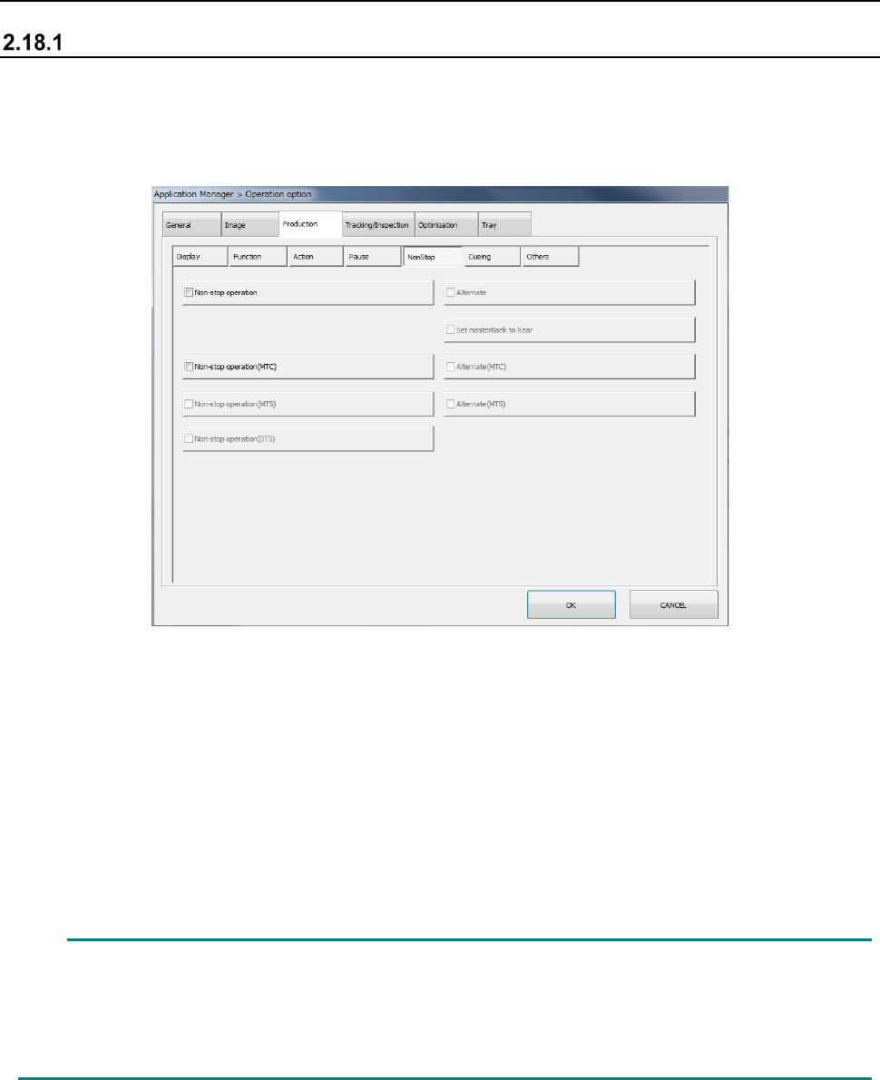
Changing the machine operation mode
To switch the operation mode, display the “NonStop” tab of the “Production” tab invoked from the
“Operation option” screen.
When you check off the “Non-stop operation (MTC)” check box, the “Non-stop operation (MTS)”
check box and/or the “Non-stop operation (DTS)” check box on the “NonStop” tab of the “Production”
tab, the MTC, MTS and/or DTS is (are) put in “Non-stop operation mode.”
In Non-stop operation mode, priority is given to pick-up of components from the main stacker.
Even while a component is being picked up from the sub stacker, the next component is picked up
from the main stacker when the main stacker is refilled with components.
When you check off the “Alternate (MTC)” check box and/or the “Alternate (MTS)” check box, the
MTC and/or the MTS is (are) put in “Alternate production mode.” In Alternate production mode, the
stackers are switched alternately if components run out on either of the stackers during PWB
production for using the MTC or the MTS in Non-stop operation mode (that is, even though the main
stacker is refilled with components, components continue to be picked up from the sub stacker until
components run out at the sub stacker).
When you make these settings on the main unit, the same settings are made at the MTC/MTS
automatically.
In the same manner as the main unit, the Non-stop operation function cannot be performed for
the MTC/MTS unless data for Non-stop operation is prepared with a production program (that is,
the same type of components are prepared at the main stacker and the sub stacker).
However, if data not for Non-stop operation is used in Non-stop operation mode, these devices
function normally although the Non-stop operation function is not performed.
Part 1 Basic Operation Chapter 2 Production
2-178
Production operation
When production starts
(1) When the main stacker is enabled, components are pull out from the main stacker.
(2) When the main stacker is disabled and the sub stacker is enabled, components are pulled out
from the sub stacker.
(3) When both the main stacker and the sub stacker are disabled, the machine displays the “Retry
List” screen, and it is put in the pause state.
When components run out
When components run out, the mini revolving lamp lights, and the lamp of the stacker switch that
indicates the condition of the stacker on the corresponding side goes off.
(1) Since the stacker is disabled, detach the stacker from the machine.
(2) Replace the tray on which components run out with another one, and then set the stacker on
the machine.
(3) Press the stacker switch to enable the stacker.
The revolving lamp indicating that components run out goes off.
Component discarding operation
Components of the MTC/MTS are not discarded, and they are to be returned to the tray from which
they are pulled out.
Even though the system aborts production without finishing it completely, components are returned
to the tray pulled out.
Note that components are not returned to a tray in the following cases:
(1) The IC collection belt is used for a component to be recognized with a VCS.
(2) Protection of a component to be recognized with a VCS is selected.
(3) The shuttle pad of the MTC is a mechanical chuck type (for components such as a BGA
component).
(4) An error that prevents a component from being collected has occurred.
Stacker switch
This switch allows you to select whether components can be pulled out from the corresponding
stacker, the main stacker or the sub stacker.
If you press this switch when the lamp inside the switch does not light, the stacker is enabled.
(The lamp lights up due to this operation. However, if the stacker is not set on the machine
normally, the lamp does not light and the stacker is not enabled either.)
While the lamp is lighting, it indicates that components will be pulled out. When the lamp does not
light, components will not be pulled out.
(1) Every time you press this switch when the stacker is set on the machine normally, the lamp
lights/goes off repeatedly (that is, the stacker is enabled/disabled repeatedly).
If you press the switch during production to disable the stacker, the stacker cannot become
able to be refilled with components immediately. Unless the switch lamp geos off completely
(it flashes during operation), the stacker cannot be refilled with components, and the door lock
cannot be unlocked.
(2) Even though you press the switch when the stacker is not set on the machine normally, the
switch does not light.
(3) When you cause the machine to enter “JUKI standard mode” on the “Operation option” screen,
both of the lamps of the main and sub stackers go off by your pressing the switch on either of
the stackers, and the door interlocks of both stackers are unlocked.