RS-1_instruction manual.pdf - 第760页
Part 2 D etaile d Descript ion of E ach Functi on Chapter 8 Machine Set up 8- 52 Host Line Connection When you se lect [Host Line Connect i on], the “ H ost Line Connect ion ” screen appears. Make setti ngs of the Int el…
Part 2 Detailed Description of Each Function Chapter 8 Machine Setup
8-51
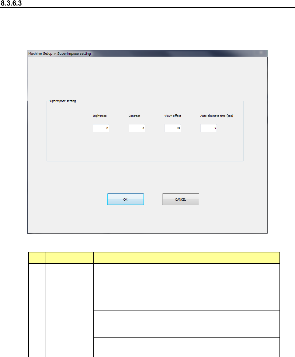
Super Impose setting
When you select the [Super Impose setting] command, the following screen appears.
When you select this command, you can make various settings of the superimpose screen.
Settings you changed are enabled only after you quit this application utility, save them and start
up the system again.
(1) Setting items
No. Item Description
1
Super Impose
setting
Brightness
A positive value makes the screen brighter,
while a negative value makes it darker.
Contrast
A positive value makes the contrast of the
screen stronger, while a negative value makes
it weaker.
VRAM offset
Set the number of lines of the image area shot
by the camera and recorded in the VRAM to be
offset in the Y direction.
Auto eliminate
time
Set the time up to auto elimination.
(2) How to set
1) Enter each value from the software keyboard.
Part 2 Detailed Description of Each Function Chapter 8 Machine Setup
8-52
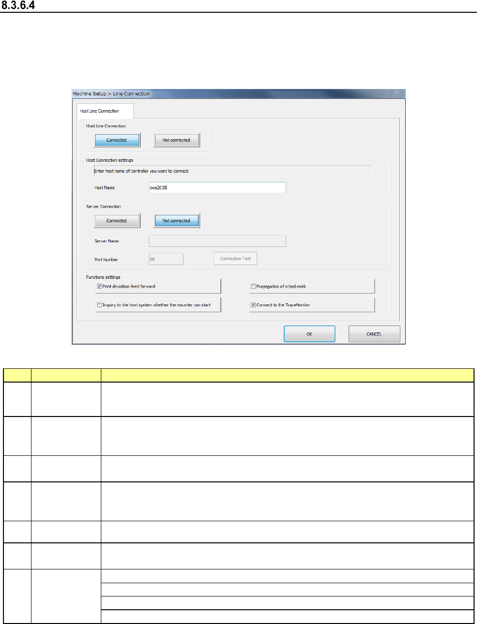
Host Line Connection
When you select [Host Line Connection], the “Host Line Connection” screen appears.
Make settings of the Intelligent Feeder System (IFS-NX) and/or the External Output Function
here.
* Refer to the “IFS-NX INSTRUCTION MANUAL” and/or the “External Output Function
INSTRUCTION MANUAL” for setting of the IFS-NX and/or the External Output Function.
(1) Setting item
No.
Item
Description
1
Host Line
Connection
Select the <Connected> button to connect this machine to the host online.
When you select the <Not connected> button, settings of all items are disabled.
2 Host Name
Set the host computer to be used for connection (host computer name or IP
address).
* Set the IP address according to the instruction of your network administrator.
3
Server
Connection
Select the <Connected> button to connect the machine to the server.
When you select the <Not connected> button, the settings of all items are disabled.
4 Server Name
Specify the server (computer name or IP address) used for connection.
* Specify the IP address according to the instruction given by your network
administrator.
5 Port Number Enter the port number of the server option in the range of 0 to 65535.
6
Connection
Test
Run the connection test for the Component Database of the server specified with
the server option.
7
Functions
settings
Set the use/non-use of the print offset feed forward function.
Set the use/non-use of the upper system start execution request function.
Set Bad Mark Propagation Function.
Set use/not use of [TraceMonitor Function].
(2) How to set
1) Use the corresponding radio button to select whether to connect to the host online or not
individually.
2) Enter the host name from the software keyboard individually.
Part 2 Detailed Description of Each Function Chapter 8 Machine Setup
8-53
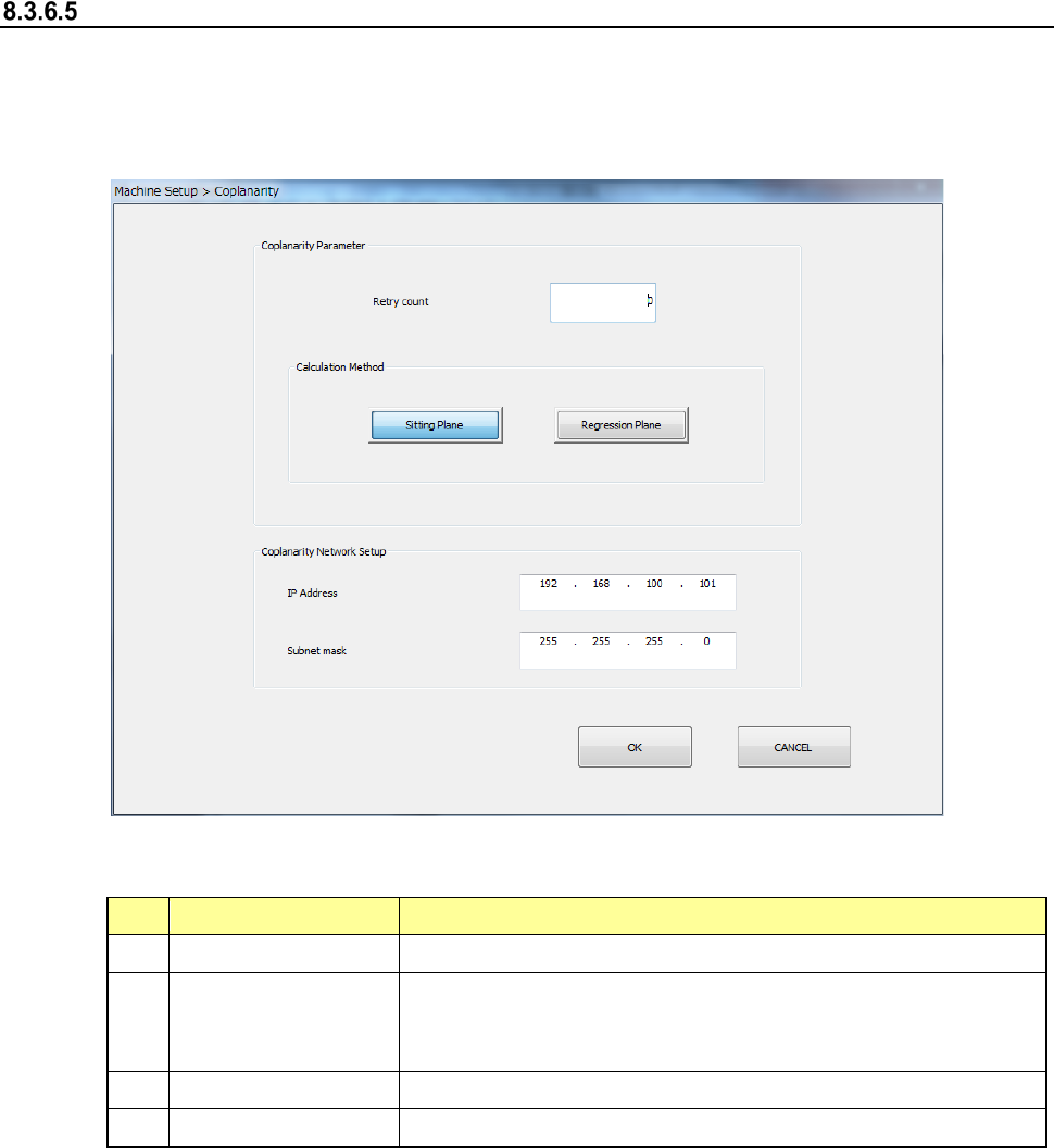
Coplanarity
When you select the [Coplanarity] command, the following screen appears.
This screen allows you to set the coplanarity parameters: the number of retries (in the “Retry
count” field) and the method for calculating the reference plane (in the “Calculation Method”
column).
(1) Setting items
No.
Setting item
Description
1
Retry count
Enter the number of retries. You can enter a value from 0 to 10.
2
Calculation Method
Select the method for calculating the reference plane, “Sitting
Plane” (three-point method) or “Regression Plane” (least square
method).
3
IP Address
Set the IP address assigned to the coplanarity unit.
4
Subnet mask
Set the subnet mask assigned to the coplanarity unit.