RS-1_instruction manual.pdf - 第58页
Part 1 B asic O peration Chapter 1 Overv iew of the Machine 1- 40 (4) Appl icable compo nent s 1) Laser recog niti on Component nam e Lead pitch/(s ize) Component siz e Remar ks Square chip resis tor 03015, 04 02, 0603, …
Part 1 Basic Operation Chapter 1 Overview of the Machine
1-39
(3) For component with a diagonal line length of 86 mm or more
The vertical opening of the LNC120-8 is 91 mm. It must be operated at a position lower than LNC
120 - 8. as a component (margin, 5 mm) with a diagonal line length of 86 mm or does not enter
the opening.
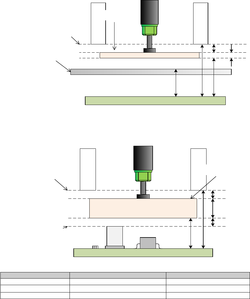
Since RS-1/1R is a mechanism by which VCS light goes up and down in the cylinder, when
attracting image recognition components, it operates with a category of 12 mm or more that does
not interfere with the top face of the VCS light.
XY-axis movable height (15 mm) + component height + margin (3 mm) <LNC 120 - 8 bottom height
(28mm)
In the case of tray holder supply, it operates in category 20 mm or more so as not to interfere with
the regulation bar.
XY-axis movable height (23 mm) + component height + margin (3 mm) <LNC 120 - 8 bottom height
(28mm)
2mm
LNC120下面高さ
XY軸移動可能高さ
部品
23mm
レギュレーションバー
28mm
3mm
14
.84mm
Fig. VCS recognition height
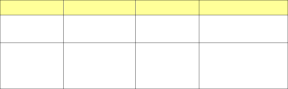
It will also consider the height of placed components and operate it.
Placed component height + margin (3 mm) + component height + margin (3 mm)
< LNC 120 - 8 bottom height (28mm)
3
mm
LNC
120下面高さ
XY軸移動可能高さ
部品
3mm
搭載済み部品
の最大高さ
15mm
28mm
10mm
The case of the mounted component height is 12 mm
Supply equipment
Height of the placed components
Maximum component height
Feeder
12mm
10mm
Tray holder
12mm
2mm
TR8SR
12mm
2mm
Regulation bar
Height of bottom surface
of LNC120-8
XY-axis movable height
Component
Height of bottom surface
of LNC120-8
XY-axis movable height
Height of the placed
components
Component

Part 1 Basic Operation Chapter 1 Overview of the Machine
1-40
(4) Applicable components
1) Laser recognition
Component name Lead pitch/(size) Component size Remarks
Square chip resistor
03015, 0402, 0603,
1005, 1608, 2012, 3216,
3225, 5025, 6432
Note: If a 03015 component cannot be
recognized with laser stably due to its
shape (for example, if a string art image
is not displayed normally), use a VCS
(10-mm field of view camera) (optional).
Network resistor
(Excluding an SOP, SOJ
and PLCC types)
MELF resistor
1.6×φ1.0, 2.0×φ1.25,
3.5×φ1.4, 5.9×φ2.2
Laminated ceramic
capacitor
0402, 0603, 1005, 1608,
2012, 3216, 3225, 4532,
5750, 5632
Tantalum chip capacitor 3216, 3528, 6032, 7343
Aluminum electrolytic
capacitor
Lead width:
0.2 mm to 3.5 mm
Height: 6.0 or less
Height: More than 6.0
to 10.5 mm
GaAsFET
Lead width:
0.2 mm to 3.5 mm
Chip film capacitor
6.5 x 4.5 x 2.7 to
10.5 x 7.2 x 5
Variable trimmer
capacitor, Chip
potentiometer, trimmer
Chip ferrite bead
1005, 1608, 2012, 3216,
3225
Cylindrical shape
Chip inductor
1005,1608,
2012,3216,3225
SOT
Mold section 1608/2012
SOT-23, SOT-89,
SOT-143, SOT-223
SOP, TSOP, HSOP
Pitch
0.65/0.8/1.0/1.27mm
(Note 1)
SOJ Pitch 0.65/1.27mm
PLCC Pitch 1.27mm
Part 1 Basic Operation Chapter 1 Overview of the Machine
1-41
Component name Lead pitch/(size) Component size Remarks
Q F P,
B QF P,
QFN
Pitch:
0.65/0.8/1.0mm
(Note 1)
BGA
Pitch: 1.0 mm or more, and
less than 2.0 mm
(when zigzag alignment: 3.0
mm or less)
(Ball diameter: 0.4 mm or
more, and 1.0 mm or less)
(Note 3)
Note 1: Even a component whose lead pitch is regulated respectively such as a QFP can be recognized
with a pitch not described above.
(This machine shall be able to recognize a pitch not described in the table above with considering
variation in lead pitches.) In such a case, a pitch within a range of the minimum one to the
maximum one can be recognized. Note that a pitch from 0.38 mm can be recognized if the
minimum pitch is 0.4 mm.
Note 2: The size of a component that can be recognized varies depending on a nozzle to be used.
The No. 1 and No. 8 nozzles can be applied to up to ☐20 mm (See Note 6), No. 2 and 7 nozzles
can be applied to up to ☐35 mm, and the No. 3, 4, 5 and 6 nozzles can be applied to up to ☐50
mm.
Note 3: Since the external shape of a component is recognized with laser of the LNC120-8, any component
cannot be placed on a board with regarding a lead or a ball as the reference position.