RS-1_instruction manual.pdf - 第34页
Part 1 B asic O peration Chapter 1 Overv iew of the Machine 1- 16 Handling an HMS The HMS (He i ght Me asurement Syste m ) is an optio nal device us ed to det ect the he ight of a component s uch as a fee der pick positi…
Part 1 Basic Operation Chapter 1 Overview of the Machine
1-15
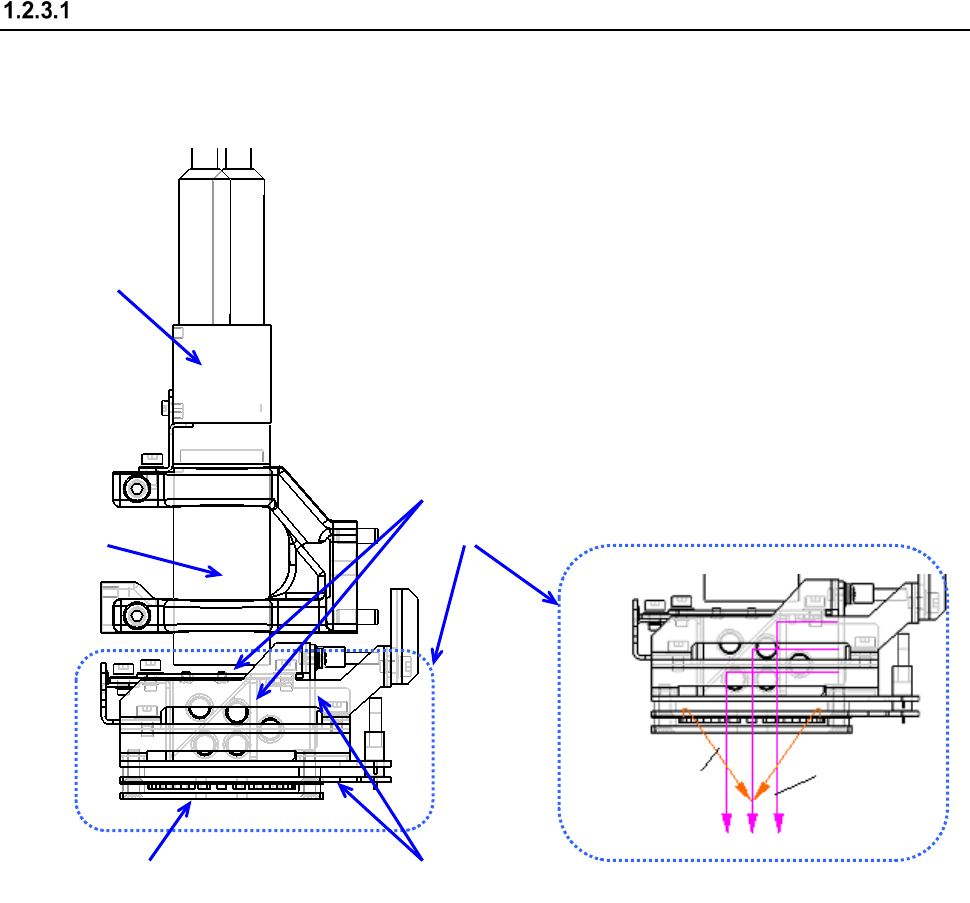
Configuration of the OCC
The camera detects a BOC mark and corrects the detected mark automatically.
The machine is equipped with a coaxial light and polarizing filter as the standard devices.
* The light for the OCC is controlled to be turned on according to the time for the click of the
shutter of the camera to shoot an image.
Therefore, if you teach a position or some other substance, the OCC light flashes
continuously.
①
CCD camera
② OCC lens
③ OCC light unit
④ Polarizing filter
⑤ Illumination LED board
Vertical light
Inclined light
②
③
④
④ ⑤
①
Part 1 Basic Operation Chapter 1 Overview of the Machine
1-16
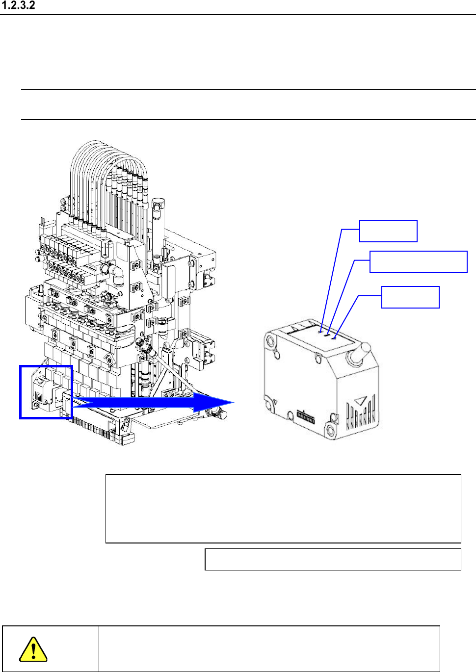
Handling an HMS
The HMS (Height Measurement System) is an optional device used to detect the height of a
component such as a feeder pick position.
This system consists of: the height displacement sensor (sensor section and PWB section)
attached on the head.
NOTE: The controls and switches located on the HMS board are all already set at the factory.
Do not change their settings.
♦ The HMS conforms to Class 2 Laser Safety Standard of JIS C6802.
It can be used safely when following the instructions described in this manual.
CAUTION
The laser used for the height sensor emits visible beams.
Do not look at these beams or touch them directly in any case.
Range display lamp ON
NEAR/FAR lamp ON: Measurement center distance ±2 mm
NEAR lamp ON: Near distance side in the measurement range
FAR lamp ON: Far distance side in the measurement range
NEAR/FAR lamp blinking: Out of the measurement range
Laser life display lamp blinking: End of laser life
NEAR lamp
FAR lamp
Laser life display lamp
Part 1 Basic Operation Chapter 1 Overview of the Machine
1-17
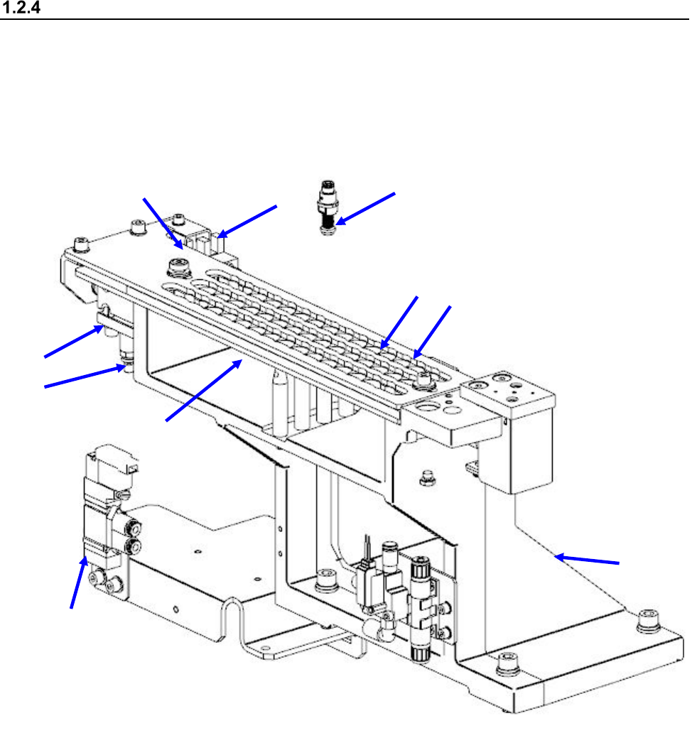
Configuration of the ATC unit (Automatic tool changer)
<When an RS-1 or an RS-1XL is used>
The slide plate ② is opened and closed by the air cylinder ④ to store or attach/detach the nozzle
⑧.
The ATC OPEN sensor ⑥ and the ATC CLOSE sensor ⑦ detect whether the slide plate ② is
opened or closed, and the speed controller ⑤ adjusts the speed for opening or closing the slide
plate.
ATC number 1-45
① ATC base ⑥ ATC OPEN sensor
② Slide plate ⑦ ATC CLOSE sensor
③ ATC base plate ⑧ Nozzle
④ Air cylinder ⑨ 5-port switching electromagnetic valve
⑤ Speed controller ⑩ ATC number
<When an RS-1R is used>
①
②
③
④
⑤
⑧
⑨
⑩
⑦
⑥