RS-1_instruction manual.pdf - 第64页
Part 1 B asic O peration Chapter 1 Overv iew of the Machine 1- 46 3) H eight ran ge of components t o be pl aced o n boards and that of the b oard rear side when transported *1: Chan ge with sof tware 1/ 3/ 6/12/20/25 m …
Part 1 Basic Operation Chapter 1 Overview of the Machine
1-45
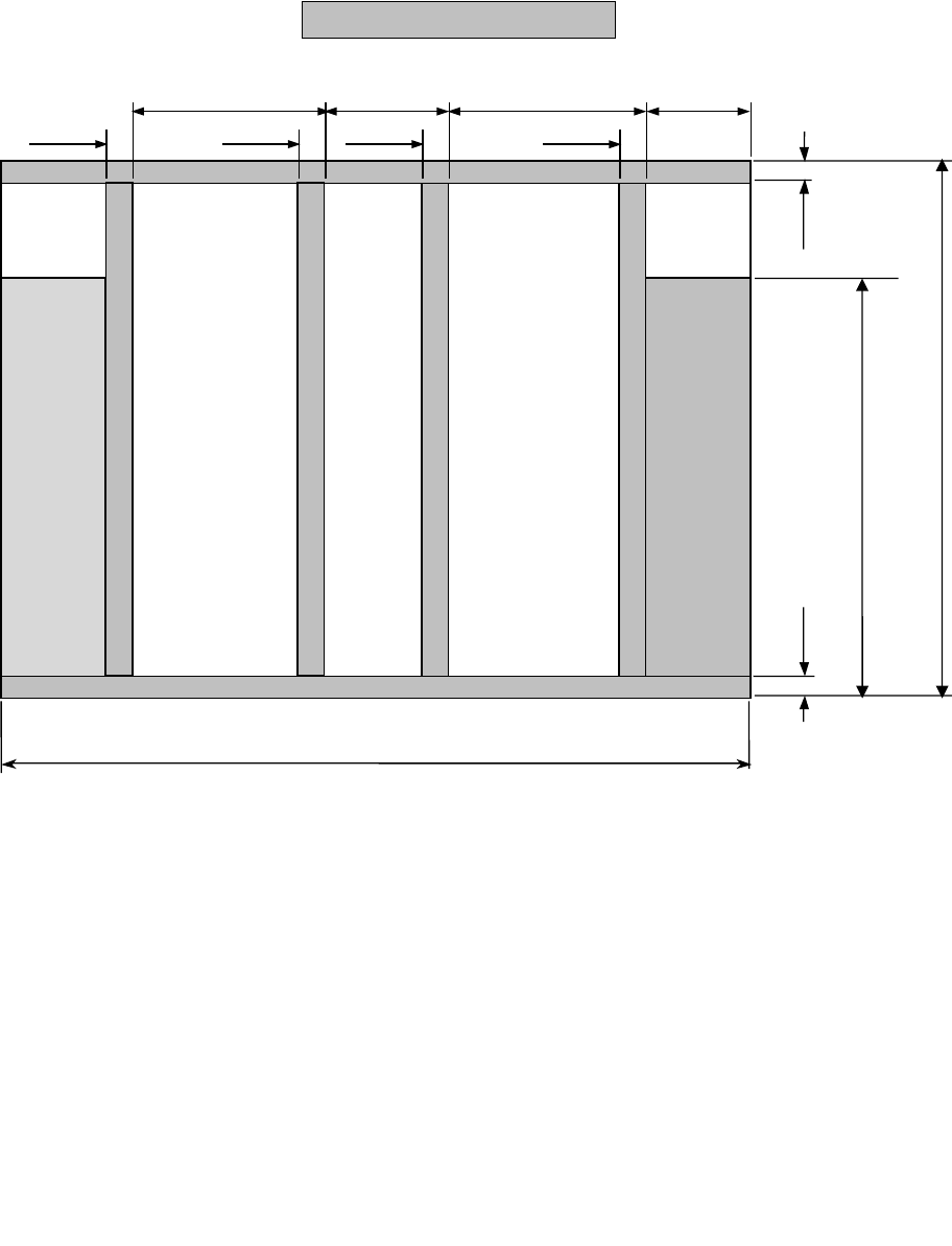
2) Bottom side of a board
Any support pin cannot set in this area range.
Standard specification:
50 to 370mm
Extra
-
large specification:
50 to 560mm
3mm
3mm
57.5mm
8mm
8mm
220mm
87mm
8mm
8mm
220mm
Left → Right
flow
Stopper movable range 0 to 320mm
Left ← Right
flow
Conveyor rail fixed side 50 to 650 mm
Part 1 Basic Operation Chapter 1 Overview of the Machine
1-46
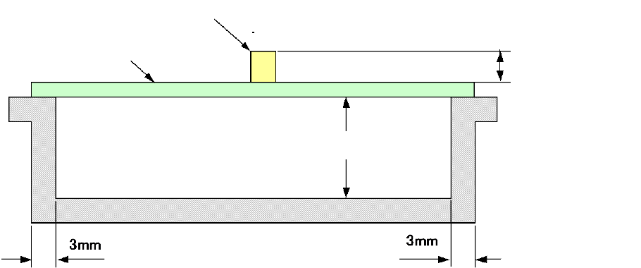
3) Height range of components to be placed on boards and that of the board rear side when
transported
*1: Change with software 1/3/6/12/20/25 mm according to the component height
*2: The height of an existing component that has been mounted should be within the
component height specification.
*3: For the component height of the laser recognition component, see "1-5 Applicable
components, (2) Recognition height of laser recognition component; for the component
height of the image recognition component, see "1-5 Applicable components, (3)
Recognition height of image recognition component".
PWBs clamping method
This is a method to use the PWB top surface as a reference to have both the PWB front and rear
ends each at the fixed and movable sides supported to the transport rails, then, to clamp the
PWBs.
PWB width adjusting methods
Standard: Automatic PWB width adjusting method via a motor
Board
Component
Area of the rear side of a board in
which a component can be placed
Maximum 40 mm
*1
Part 1 Basic Operation Chapter 1 Overview of the Machine
1-47
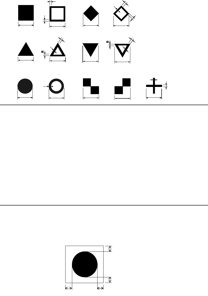
(3) Board Recognition Marks
1) Shape
Create the board recognition marks under the following conditions.
We recommend the filled circle for the mark.
A
C
C
A
B
A
B
B
A
B
A
B
C
C
B
B
B
B
A
C
B
A
C
B
B
Notes:
1. When recognition, the mark shall be placed in the angle shown above.
However, if you specify "Use of each circuit mark" for a non-matrix PWB, the mark can be
recognized only when all marks of the reference circuit are positioned in the angle
described and the circuit is positioned at 90, 180, 270 or 360 degrees.
2. The fiducials of the same shape and same size is preferable within a board.
3. When processing, copper foil or solder plating can be recognized
4. Maximum number of marks which can be registered
Board mark: 2 set (2 marks or 3 marks)
Component positioning mark: 100 sets (Pairs of 2 marks to 3 marks)
5. Items that can be registered
Mark number, Balance detection window, Normal/reverse rotation identification when
detected, Mark shape, Outer dimensions, Effective value of projection, Matching
6. If there is no recognition mark on a board, register a user designated template to allow
the machine to recognize marks
2) Clearance
In the area around each recognition mark, there shall be a space in which any other
component such as a conductor pattern, solder resist and marking is not located.
The dimensions of this space should be a square whose size is larger than the outer area of a
recognition mark by 0.5 mm or more in the X direction and 0.5 mm or more in the Y direction.
A and C sizes:
0.5 to 3.0 mm ± 10 % or
lower
B size:
0.2 mm or longer
Circle
Square
Diamond
Regular
triangle
Up-side-down
triangle
Checker
pattern (1)
Cross
Inside-blank
circle
Inside-blank
square
Inside-blank
diamond
Inside-blank
up-side-down triangle
Checker
pattern (2)
Inside-blank
Regular triangle
0.5 mm or more
0.5 mm or more
0.5 mm or more
0.5 mm or more